

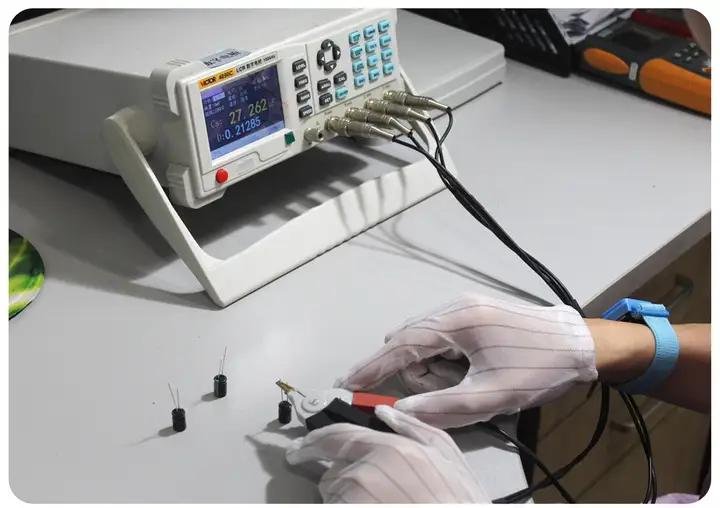
Two lines on a datasheet describe how an inductor behaves away from its nominal value: the inductor Q factor and the self-resonant frequency. The first tells you how much of the energy cycling through the part is lost as heat at a particular frequency. The second tells you the frequency beyond which the component no longer behaves as an inductor at all. Both come from parasitics that no real winding can avoid.
Designers of resonant circuits and filters rely on these figures daily, but they are just as relevant to power electronics, where a choke is expected to block noise across a wide band. This article explains what each quantity means, what determines it physically and how to apply it. It reflects test practice at NG Electronics, where Q factor is among the parameters checked on wound components.
Key takeaways
- Q is the ratio of inductive reactance to equivalent series resistance at one frequency.
- Self-resonant frequency is set by inductance and the stray capacitance of the winding.
- Above the SRF an inductor looks capacitive and its filtering falls away.
- Winding style and core material control both figures more than inductance alone.
What inductor Q factor means
Quality factor is defined as the reactance of the inductor divided by its equivalent series resistance at the same frequency, so Q equals 2π multiplied by frequency and inductance, divided by resistance. A high value means the part stores far more energy per cycle than it dissipates. The resistance in question is not the DCR alone; it includes skin and proximity effects in the copper and an equivalent resistance representing core loss.
Q is therefore a function of frequency. At low frequency reactance grows in proportion to frequency while resistance stays near the DCR, so Q rises. Further up, alternating current resistance and core loss increase faster than reactance, and Q reaches a peak and then declines. It falls to zero at self-resonance, where the net reactance vanishes. A Q value is meaningful only with its test frequency, a point stressed in how to read an inductor datasheet.
Where self-resonant frequency comes from
Every pair of adjacent turns forms a tiny capacitor, as do the winding and the core and the two ends of the coil. Lumped together, these appear as a single capacitance in parallel with the inductance. The two resonate at a frequency equal to one divided by 2π times the square root of inductance multiplied by capacitance. A 100 µH inductor with 10 pF of stray capacitance, for example, resonates at about 5 MHz.
Below that frequency impedance rises with frequency as expected. At resonance it reaches a maximum limited by losses, and above it the capacitance dominates, so impedance falls again. Measured inductance also appears to increase as the test frequency approaches resonance, which is an artefact of the parallel capacitance and not a real gain. This is one reason readings must be taken well below the SRF, as described in how to measure inductance with an LCR meter.
What determines Q and SRF in a real component
Construction has a strong influence. A single-layer winding spaced around a toroid has low capacitance, since the start and finish are far apart and adjacent turns differ little in voltage. A multilayer winding places turns with large voltage differences on top of one another and has much more capacitance, unless it is wound in sections or with a progressive technique. Larger inductance values need more turns, so their SRF is typically lower.
Core material sets the loss side. Ferrites intended for power use have low loss up to a certain frequency and then become increasingly resistive; that lossy region is exploited deliberately in suppression components. Iron powder mixes differ widely in their useful frequency range. Magnetically shielded constructions contain the stray field and so reduce coupling into nearby parts. For small-signal and converter work, drum core inductors from a shielded drum core inductor supplier are generally specified with a minimum SRF.
- Fewer layers and sectional winding reduce capacitance and raise the SRF.
- Thicker or stranded conductors lower resistance and raise Q, within skin depth limits.
- Core material must be low loss at the frequency where high Q is required.
Using Q and SRF in filters and resonant circuits
In a tuned or resonant circuit, high Q gives a sharp response and low loss, so the requirement is a minimum Q at the working frequency together with an SRF comfortably above it. In an EMI filter the priorities reverse. A filter choke with very high Q can ring with the filter capacitors and produce a peak in the response, so some loss is welcome and damping may be added on purpose.
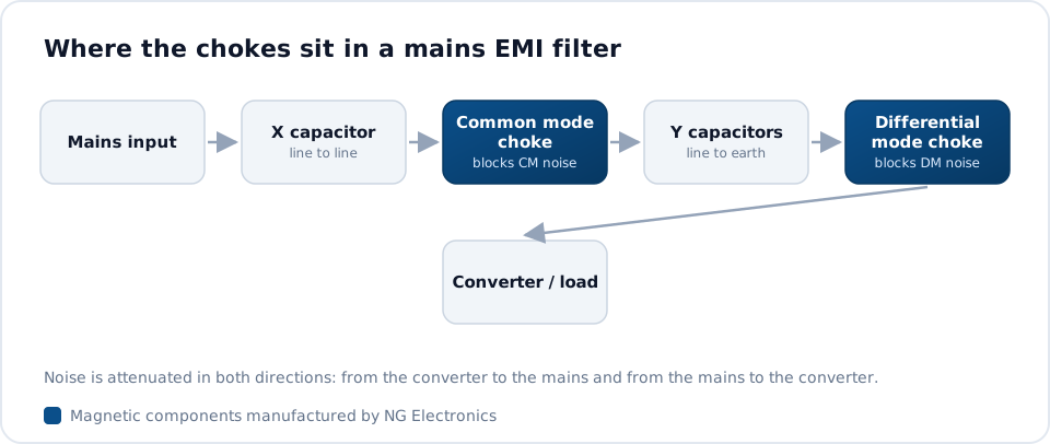
For noise suppression the useful measure is impedance across the band of interest. A choke attenuates best around its SRF and progressively less above it, so the resonance should be placed with the problem frequencies in mind. Common mode chokes are often wound in separated sections on the core for exactly this reason. Filter layout and component selection are treated in EMI filter design step by step, and an EMI filter choke manufacturer can supply measured impedance curves.
Q and SRF in power inductors
For a storage inductor in a converter, Q at a small-signal test frequency says little about efficiency under load, because loss there depends on the actual current waveform and flux swing. SRF remains relevant, though. Each switching edge contains harmonics extending to many megahertz, and the winding capacitance couples them straight through the inductor to the output. A typical guideline keeps the switching frequency below about one fifth to one tenth of the SRF.
NG Electronics is an ISO 9001:2015 certified manufacturer in Pune, India, and electrically tests 100 percent of units for inductance, DCR, Q factor, saturation current and hipot. When a design needs a particular SRF or impedance profile, such as a common mode choke for SMPS input filtering, the winding arrangement can be adjusted at the sample stage. Inductor prototype manufacturing allows two or three winding variants to be compared on your own analyser before volume production begins.
Frequently asked questions
What is a good Q factor for an inductor?
It depends on the application. Resonant and radio-frequency circuits may need Q values of 50 or more at the working frequency, while power and EMI filter chokes often work well with much lower values and can benefit from some loss for damping. Always compare Q figures at the same test frequency, since Q varies strongly with frequency.
How close to the self-resonant frequency can I operate an inductor?
For energy storage in power converters, a typical guideline is to keep the switching frequency below one fifth to one tenth of the SRF, so that the part behaves as a predictable inductance. Suppression chokes are different: they are frequently used near or around their SRF, where impedance is highest, to attenuate noise.
How can the SRF of a custom inductor be increased?
Reduce winding capacitance by using a single layer where possible, spacing the start and finish apart, winding in sections or lowering the number of turns with a higher permeability core. Each option interacts with saturation and loss, so NG Electronics normally reviews the complete specification and confirms the result by measurement on a sample.
About NG Electronics
NG Electronics is a leading ISO 9001:2015 certified manufacturer of toroidal power inductors, common mode chokes, ferrite core transformers, line filter inductors, drum core inductors and custom wound magnetic components, based in Pune, India. Every part is wound and 100% electrically tested in-house. Send your inductance, frequency range and any Q or SRF requirement to NG Electronics for a technical quotation within 24 working hours and a sample to verify on your own instruments.




