
Every inductor that carries alternating flux turns part of the energy passing through it into heat. Some of that heat comes from the copper, and the rest is generated inside the magnetic material. The second part, known as inductor core losses, is easy to overlook because it does not appear in a simple DCR calculation, yet at high switching frequencies it can equal or exceed the winding loss.
Core loss has two classical components, hysteresis and eddy currents, and both depend on how far and how fast the flux density swings. This article explains each mechanism in practical terms, shows how designers estimate the loss from published material data, and outlines the choices that keep it manageable. It draws on the materials NG Electronics winds daily, from ferrite and iron powder to alloy powder and nanocrystalline cores.
Key takeaways
- Core loss is driven by alternating flux swing and frequency, not by direct current.
- Hysteresis loss is the energy spent cycling the material around its B-H loop.
- Eddy current loss arises from circulating currents induced in the core itself.
- Material choice and flux swing are the main levers for reducing core heating.
What inductor core losses are and why they matter
A magnetic core is not a passive conduit for flux. Each time the flux density rises and falls, the material absorbs a small amount of energy that is not returned to the circuit. Multiply that energy by the switching frequency and the core volume and the result is a steady power dissipation. It appears as heat in the centre of the component, where it is hardest to remove, and it adds directly to the temperature rise caused by the winding.
The important point for a power inductor is that only the alternating part of the flux counts. A choke carrying a large direct current with small ripple has a small flux swing and low core loss, even though it may be close to saturation. The same choke with heavy ripple, as discussed in inductor ripple current explained, can run noticeably hotter at an identical load current. Loss and saturation must therefore be checked separately.
Hysteresis loss: the area inside the B-H loop
Magnetic materials are made of small regions called domains. As the applied field increases, domain walls move and the domains align; as the field decreases they do not retrace exactly the same path. Plotted as flux density against field strength, the result is a loop, and the area enclosed by that loop is the energy lost per unit volume in each cycle. A narrow loop indicates a low-loss material, a wide loop a lossy one.
Because the energy is lost once per cycle, hysteresis loss is proportional to frequency. It also rises steeply with the flux swing, typically somewhat faster than the square of the peak alternating flux density for power ferrites. Halving the flux swing therefore cuts hysteresis loss to roughly a quarter or less. This is why high-frequency designs often run the core well below saturation: the limit is heat, not the flux capability of the material.
Eddy current loss inside the core
A changing flux induces voltage in any conductor it links, and that includes the core. If the core material conducts electricity, circulating currents flow within it and dissipate power through its resistance. For a given flux swing this classical eddy current loss increases with the square of frequency, so it becomes the dominant concern as switching speeds rise. It is reduced by making the material resistive or by breaking it into electrically isolated sections.
Different materials apply those two ideas in different ways. Ferrites are ceramics with high resistivity, which is why they suit high-frequency transformers and chokes. Powder cores consist of fine metal particles separated by insulation, limiting current loops to the particle size. Laminated steel and nanocrystalline tape use thin insulated layers. The trade-offs between the two most common families are compared in ferrite versus powdered iron cores.
- Ferrite: high resistivity, low loss at high frequency, lower saturation flux density.
- Iron powder: high saturation and low cost, higher loss under large ripple.
- MPP, Sendust and High Flux: alloy powders with lower loss than iron powder.
- Nanocrystalline: thin tape with very high permeability, widely used in common mode chokes.
Estimating core loss from material data
Manufacturers of core materials publish curves of loss per unit volume against peak alternating flux density at several frequencies. Engineers commonly fit these with the Steinmetz equation, in which loss density equals a constant multiplied by frequency raised to one exponent and flux density raised to another. The exponents are empirical and valid only over a limited range, and the published curves assume sinusoidal excitation, so results for triangular or pulsed waveforms are estimates.
The practical method is straightforward. Calculate the peak-to-peak flux swing from the applied volt-seconds, the number of turns and the core cross-section, halve it to get the peak alternating value, read the loss density at the operating frequency and multiply by core volume. Loss also varies with temperature, and many power ferrites are formulated to have minimum loss near their intended operating temperature. Transformer-specific considerations appear in high-frequency transformer losses.
Reducing core loss in a real design
Four adjustments are available. Adding turns lowers the flux swing for the same volt-seconds, at the cost of more copper resistance. A larger core cross-section does the same without extra turns but increases size. Changing to a lower-loss material addresses the problem directly. Finally, reducing ripple by raising inductance cuts the swing. The lowest total loss typically occurs when core loss and copper loss are of similar magnitude, so shifting some loss between them is normal practice.
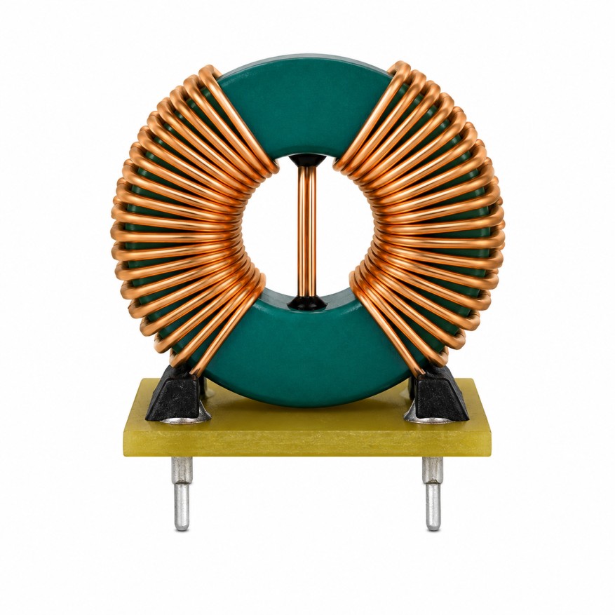
Winding loss at high frequency also needs attention, as covered in litz wire versus solid wire. NG Electronics, an ISO 9001:2015 certified manufacturer in Pune, India, builds custom wound inductors and ferrite core transformers on the material that suits the stated frequency and ripple. As a high-frequency ferrite transformer supplier and a power inductor manufacturer, we can also wind a toroidal inductor for SMPS use on alternative cores for comparison.
Frequently asked questions
What is the difference between hysteresis and eddy current loss?
Hysteresis loss is the energy needed to move magnetic domains around the B-H loop once per cycle, so it scales with frequency and strongly with flux swing. Eddy current loss comes from currents induced in the core material by the changing flux, and it scales with the square of frequency. Both appear as heat in the core.
Does direct current cause core loss in an inductor?
A steady direct current produces a steady flux, which does not cycle the material and so generates no core loss by itself. It does cause copper loss in the winding and moves the core towards saturation. Core loss is produced by the alternating component, meaning the ripple current and the flux swing it creates at the switching frequency.
Which core material has the lowest loss?
It depends on frequency and flux level. Power ferrites typically give the lowest loss at high switching frequencies, while alloy powders such as MPP offer low loss with better tolerance of direct current bias. Iron powder is economical but lossier under heavy ripple. NG Electronics can recommend a material once frequency, ripple and current are specified.
About NG Electronics
NG Electronics is a leading ISO 9001:2015 certified manufacturer of toroidal power inductors, common mode chokes, ferrite core transformers, line filter inductors, drum core inductors and custom wound magnetic components, based in Pune, India. Every part is wound and 100% electrically tested in-house. Tell NG Electronics your switching frequency, ripple current and temperature limit, and we will propose a core material and winding with a technical quotation within 24 working hours.