


EMI filter design is often left until a prototype fails its first pre-compliance scan, and by then the board space, the enclosure and the budget are already fixed. A more reliable approach treats the input filter as part of the power stage from the first schematic. The filter has one job: to stop the high-frequency noise generated by switching from travelling back along the mains or DC supply cable, while passing the low-frequency power current with as little loss as possible.
The method below applies to switch-mode power supplies, inverters, chargers and drives alike, because the physics is the same. Noise appears in two forms, each needs its own filter elements, and those elements interact with the converter and with each other. NG Electronics, an ISO 9001:2015 certified manufacturer in Pune, India, winds the common mode chokes and line filter inductors that form the inductive half of such filters, and the steps here follow the questions asked when a customer shares a failing emission plot.
Key takeaways
- Measure the unfiltered noise with a LISN and separate common mode from differential mode before choosing parts.
- Required attenuation is the measured level minus the limit plus margin, typically 6 dB or more.
- Y capacitance is capped by earth leakage current, so the common mode choke supplies most of the attenuation.
- Damping and layout decide whether the calculated attenuation is achieved on the real product.
Step 1: Start EMI filter design by measuring the noise
Every filter calculation starts from a measurement, not from a guess. Conducted emissions are measured with a line impedance stabilisation network, or LISN, which presents a defined impedance to the equipment and passes the noise voltage to a receiver or spectrum analyser. Record the unfiltered spectrum across the conducted band, typically 150 kHz to 30 MHz for mains-powered products, and note which harmonics sit closest to the limit line.
Next, separate the noise into its two modes. Differential mode noise flows out on one line and back on the other. Common mode noise flows in the same direction on all lines and returns through earth. A noise separator, or a current probe clamped first around both conductors together and then around the pair with one conductor reversed, gives a usable split. Each mode needs different components: a larger common mode choke does nothing for a differential mode problem.
Step 2: Set the attenuation target and corner frequency
The required attenuation at each frequency is the measured level minus the limit, plus a margin. Engineers typically add 6 dB or more to cover unit-to-unit variation and differences between the development bench and the test laboratory. Do this separately for the common mode and differential mode spectra. The harmonic that needs the most attenuation at the lowest frequency usually defines the filter, since a low-pass network gives less help the closer its corner frequency sits to the noise.
A single LC stage is a second-order low-pass filter with a corner frequency of 1/(2π√(LC)), and above that corner its attenuation rises at 40 dB per decade in the ideal case. If you need 40 dB at the first troublesome harmonic, the corner must therefore sit about one decade below it. When the resulting components are impractically large, two smaller stages in cascade usually occupy less volume than one large stage. Our guide on how to pass conducted emissions testing explains how to read the scan that feeds this calculation.
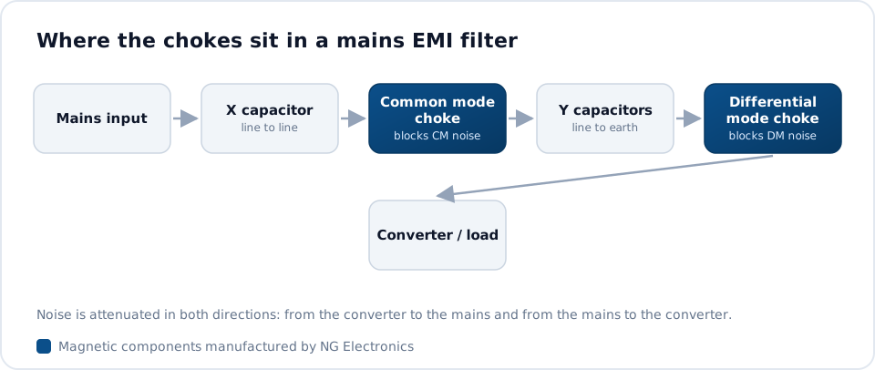
Step 3: Size the common mode stage
The common mode stage pairs a common mode choke with Y capacitors connected from each line to earth. The Y capacitance is capped by the earth leakage current permitted under the safety standard for the product, so it is normally fixed first and the choke inductance is then calculated from the corner frequency. The article on X and Y capacitors with common mode chokes covers the capacitor side in detail. Typical mains filters use chokes of a few millihenries to several tens of millihenries.
Choose the choke on four points: rated current with acceptable temperature rise, inductance at the frequency of interest and not only at the datasheet test frequency, impedance across the band, and the insulation between windings. High-permeability MnZn ferrite suits most designs, while nanocrystalline cores give more inductance per turn where space is tight. NG Electronics builds both, from 250 mA PCB parts to 50 A ring-core designs, and its EMI filter choke manufacturing page describes the standard range.
Step 4: Design the differential mode stage
Differential mode noise is attenuated by X capacitors across the lines working against series inductance. Part of that inductance comes at no extra cost: the two windings of a common mode choke never couple perfectly, and the resulting leakage inductance of the common mode choke acts as a small differential mode inductor. In low-power supplies this, together with one or two X capacitors, is often sufficient to bring the lower harmonics under the limit.
At higher power, or where low-frequency harmonics are strong, add a dedicated differential mode inductor. Unlike the common mode choke, it carries the full line current as magnetising flux, so it must be checked against saturation at peak current, including inrush and the crest of the mains waveform. Iron powder and other distributed-gap cores are the usual choice. A specialist AC line filter choke manufacturer can supply these as separate parts or as combined common and differential mode assemblies on one base.
Step 5: Damp, lay out and verify the filter
An undamped LC filter resonates at its corner frequency, and a regulated switching converter presents a negative incremental input resistance that can make this worse. The standard guidance is to keep the filter output impedance well below the converter input impedance across frequency, and to add damping where the resonant peak is sharp, typically a resistor in series with a capacitor placed across the filter capacitor.
Layout decides whether the calculated attenuation is achieved. Keep filter input and output tracks apart so noise cannot couple around the components, give Y capacitors short connections to the chassis, and keep the choke away from the stray field of the main transformer. Then re-measure with the LISN and compare with the target. If you are filtering a switch-mode supply, our common mode choke for SMPS page shows typical constructions, and NG Electronics can supply samples for this verification stage.
Frequently asked questions
How much margin should I leave below the emission limit?
A margin of about 6 dB below the limit on a pre-compliance scan is a typical target. It allows for component tolerances, variation between production units and differences between your bench set-up and an accredited laboratory. Choke inductance in particular varies with core permeability tolerance and temperature, so check the worst-case inductance, not only the nominal value, when you calculate the margin.
Is one filter stage enough, or do I need two?
One LC stage per noise mode is enough for many low-power products. If the attenuation needed at the lowest noise harmonic exceeds what a single stage can deliver with practical component sizes, split the filter into two cascaded stages. Two stages also help at high frequency, where the parasitic capacitance of a single large choke would otherwise let noise pass.
What is needed to specify a custom choke for an EMI filter?
A custom choke is specified by line voltage, rated and peak current, target inductance or impedance, the frequency range of concern, the insulation requirement and the available footprint. With that information a manufacturer can propose a core material, winding style and base, then supply samples for laboratory approval before production. Custom samples are typically ready within 7 to 10 working days.
About NG Electronics
NG Electronics is a leading ISO 9001:2015 certified manufacturer of toroidal power inductors, common mode chokes, ferrite core transformers, line filter inductors, drum core inductors and custom wound magnetic components, based in Pune, India. Every part is wound and 100% electrically tested in-house. Send your emission plot, line current and target inductance to NG Electronics at sales@ngelectronics.in for a technical quotation within 24 working hours. Overseas enquiries are welcome.




