
Anyone can clip a component into a fixture and read a value, yet two laboratories often disagree about the same part by several percent. Learning how to measure inductance with an LCR meter properly means understanding what the instrument actually does: it applies a small alternating signal, measures the voltage and current with their phase difference, and calculates an impedance that it then expresses through a chosen equivalent circuit.
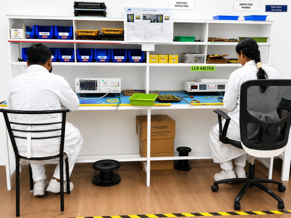
Each of those steps involves a setting, and each setting can shift the answer. This guide covers the choices that matter, in the order you would make them at the bench, and then lists the usual causes of disagreement between supplier and customer readings. It follows the routine used at NG Electronics, an ISO 9001:2015 certified manufacturer in Pune, India, where LCR testers are used to check inductance on every unit produced.
Key takeaways
- Match the test frequency and signal level stated on the datasheet or drawing.
- Use the series model for low-impedance parts and the parallel model for high-impedance parts.
- Carry out open and short compensation whenever the fixture or leads change.
- An LCR meter reading is small-signal inductance without direct current bias.
What an LCR meter actually measures
The meter drives the component with a sine wave at a selected frequency and amplitude, then measures the magnitude and phase of the resulting impedance. From those two quantities it derives inductance together with a secondary parameter such as Q, dissipation factor or equivalent resistance. The inductance shown is therefore a calculated quantity that depends on the equivalent circuit selected, the frequency and the drive level, not a fixed property read directly.
It is also a small-signal measurement. The test current is typically a few milliamperes or less, so the core operates at a tiny flux density with no direct current bias. The reading corresponds to the initial inductance on a datasheet. It does not show how the part behaves at rated current, which requires a bias source or a pulse-based saturation test, both described in testing inductors and transformers.
Step-by-step: how to measure inductance with an LCR meter
First set the frequency. Use the value on the datasheet; common choices are 1 kHz for large inductances, 10 kHz for mains filter chokes and 100 kHz for small power inductors. If nothing is stated, pick a frequency at which the reactance is conveniently between a few ohms and a few kilohms, and well below the self-resonant frequency. Next set the signal level, again following the datasheet, because high-permeability ferrite cores change inductance noticeably with drive level.
Then compensate the fixture, connect the part and read the value once the display settles. Record frequency, level and model alongside the result so the measurement can be repeated. Before fitting parts to a board, comparing the reading with an estimate from the inductance calculator is a quick sanity check on turns count and core material. Keep the component away from steel bench surfaces and other magnetic objects, which can disturb open-core parts.
- Select frequency and signal level to match the specification.
- Choose the series or parallel equivalent circuit.
- Perform open and short compensation with the actual fixture.
- Connect with four-terminal Kelvin contacts and take the reading.
- Record all conditions with the result.
Series or parallel model: Ls versus Lp
The meter can represent the part as an inductance in series with a resistance, giving Ls, or in parallel with a resistance, giving Lp. For a low-loss component the two values are almost identical. They diverge as Q falls, because the same measured impedance is being split in two different ways. A reading taken in the wrong mode on a lossy part can differ from the specification by more than the tolerance.
As a general rule, use the series model when the impedance is low, typically below about 100 Ω, since winding resistance is then the significant loss. Use the parallel model when the impedance is high, typically above about 10 kΩ, since core loss and stray capacitance act in parallel. Between those values either may be used, provided both parties use the same one. Most power inductors and chokes are specified in series mode.
Fixtures, compensation and lead effects
Test leads have their own inductance, resistance and capacitance. Open compensation measures the stray admittance of the fixture with nothing connected, and short compensation measures its residual impedance with the contacts joined by a low-inductance link. The meter then subtracts both. Without this step, a few centimetres of lead can add tens of nanohenries, which is a large error on a 1 µH part and negligible on a 10 mH choke.
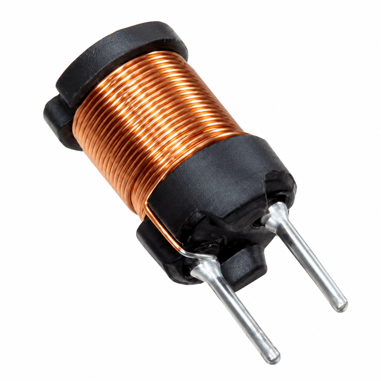
Four-terminal Kelvin connections separate the current-carrying contacts from the voltage-sensing ones, removing contact resistance from the result, which matters for low-value inductors and for DCR. Keep the lead geometry unchanged after compensation, since moving the cables alters their inductance. For leaded parts such as toroidal power inductors, measure at a consistent point on the leads, and make sure enamel is fully removed where the contacts touch.
Why readings disagree and how to resolve it
Most disputes trace back to a handful of causes: different test frequency, different signal level, series against parallel mode, missing compensation, or temperature. Ferrite permeability changes with temperature, so a part measured in a cold stores area may differ from the same part at 25 °C. Measuring too close to self-resonance inflates the apparent inductance, as explained in inductor Q factor and self-resonant frequency. Agreeing a written test condition on the drawing removes nearly all of these.
Multi-winding parts need extra care. Leakage inductance is measured on one winding with the others shorted, and common mode chokes are measured on one winding with the other open; details appear in transformer testing and design validation. NG Electronics supplies a test certificate with orders on request and documents its checks on the quality assurance page. Buyers evaluating an inductor manufacturer in Pune, a choke coil manufacturer in India or any OEM inductor manufacturer should ask for the test conditions behind each reported value.
Frequently asked questions
What frequency should I use to measure inductance?
Use the frequency given on the datasheet or drawing. If none is given, choose one where the reactance is between a few ohms and a few kilohms and which is far below the self-resonant frequency. Typical choices are 1 kHz for large inductances, 10 kHz for line filter chokes and 100 kHz for small power inductors.
Can an LCR meter measure saturation current?
Not by itself. A standard LCR meter applies only a small alternating signal, so it reports initial inductance. Saturation current is found by superimposing a direct current from a bias supply while measuring inductance, or by applying a voltage pulse and observing where the current ramp steepens. Dedicated bias units and saturation testers are used for that purpose.
Why does my reading differ from the supplier's test certificate?
Check that frequency, signal level and series or parallel mode match the certificate, and that open and short compensation were performed with your fixture. Temperature and lead length also influence the result. If a difference remains after aligning the conditions, NG Electronics can share the batch record, which gives traceability to raw material and production date.
About NG Electronics
NG Electronics is a leading ISO 9001:2015 certified manufacturer of toroidal power inductors, common mode chokes, ferrite core transformers, line filter inductors, drum core inductors and custom wound magnetic components, based in Pune, India. Every part is wound and 100% electrically tested in-house. Need wound components supplied with measured data? Send your specification and preferred test conditions to NG Electronics for a technical quotation within 24 working hours.