


Knowing how to read an inductor datasheet is a quiet skill that prevents a surprising number of field failures. Two parts can both be labelled 47 µH and 5 A and still behave very differently on the bench, because one manufacturer defines current at a 10 percent inductance drop and another at 30 percent, or because one rating assumes a large copper test board that your layout does not provide.
This article goes through a typical datasheet line by line and explains what each figure means, how it was measured and what to check before committing a part to a design. The examples reflect how NG Electronics, an ISO 9001:2015 certified manufacturer in Pune, India, records and reports the electrical tests carried out on its wound components, so the same reasoning applies to catalogue parts and to custom drawings.
Key takeaways
- Inductance is only meaningful together with its test frequency, test level and tolerance.
- Saturation current and RMS current are separate limits with different physical causes.
- DCR is usually quoted at 20 or 25 °C and rises as copper heats up.
- Curves of inductance against current and temperature tell more than the headline table.
Inductance, tolerance and the test conditions behind them
The headline inductance is measured with a small alternating signal and no direct current, typically at 1 kHz, 10 kHz or 100 kHz and at a low voltage level stated in the notes. That figure is the initial inductance. It tells you nothing yet about the value under load, and it will differ slightly if measured at another frequency or drive level. When comparing two suppliers, confirm that the test conditions match before comparing the numbers.
Tolerance is usually given as a letter code or percentage, with plus or minus 10 or 20 percent common for power parts. A converter must work at both ends of that band: the low limit gives the highest ripple and peak current, while the high limit affects loop response. Our guide to measuring inductance with an LCR meter shows how to reproduce the datasheet condition when checking incoming samples in your own laboratory.
Saturation current and RMS current are different ratings
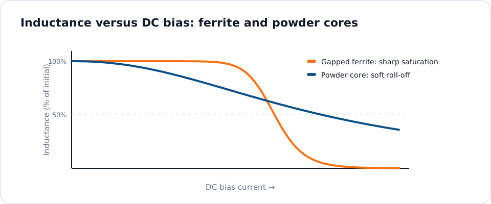
Saturation current, often written Isat, is the direct current at which inductance has fallen by a stated percentage from its initial value. The percentage varies between manufacturers and between core materials, so a 30 percent figure cannot be compared directly with a 10 percent figure. Compare your worst-case peak current, including start-up and overload transients, against Isat at the highest core temperature, since ferrite saturation flux density typically falls as temperature rises.
RMS or thermal current, written Irms or Idc, is the current that produces a stated temperature rise, commonly 40 °C, through copper loss alone. It is measured in still air on a defined board, so the cooling in an enclosed product may be worse. The relationship between these ratings is covered in inductance, saturation current and DCR explained, and our note on inductor temperature rise and derating shows how to adjust the figure for a hot ambient.
- Check peak current against Isat and the stated inductance drop.
- Check RMS current against Irms and the stated temperature rise.
- Use the lower margin of the two as the limiting factor.
DCR, self-resonant frequency and Q
Direct current resistance is the resistance of the winding, quoted as a typical or maximum value at 20 or 25 °C. Copper resistance increases by roughly 0.4 percent per kelvin, so a winding at 100 °C has about 30 percent more resistance than the datasheet figure. Use the maximum, corrected for temperature, when estimating conduction loss and efficiency. A lower DCR for the same inductance generally means a larger part or a core closer to saturation.
Self-resonant frequency, SRF, is the point at which the winding capacitance resonates with the inductance. Above it the component looks capacitive. A common rule of thumb is to keep the operating frequency well below the SRF, typically by a factor of five or more for power conversion. Q factor, where given, indicates loss at a specific frequency and matters most in filters and resonant circuits; both terms are explained in Q factor and self-resonant frequency.
How to read an inductor datasheet curve by curve
The graphs usually carry more information than the table. The inductance against direct current curve shows whether saturation is abrupt, as with gapped ferrite, or gradual, as with iron powder and alloy powder cores. A soft curve lets you operate further along it with predictable results. The temperature rise against current curve reveals the thermal margin, and an impedance against frequency plot confirms the SRF and the useful filtering band.
Some datasheets add core loss charts or a loss calculation tool, which matter once ripple current becomes a large fraction of the load current. If a curve you need is missing, ask for it. For catalogue drum core inductors and wound toroids, a manufacturer should be able to supply measured data on request, and for a toroidal inductor for SMPS duty it is reasonable to request inductance at your actual peak current.
Mechanical, environmental and compliance details
Dimensions, pad layout, lead diameter and mounting style decide whether the part fits the board and survives vibration. Check the operating temperature range and note whether it includes self-heating; many ranges do, meaning ambient plus rise must stay within the upper limit. Insulation class, hipot voltage between windings and core, and the wire grade are relevant wherever the component bridges a safety barrier or sits close to a heatsink.
Finally, look for material declarations and test coverage. NG Electronics uses RoHS and REACH compliant materials, with certificate copies available on request, and tests 100 percent of units electrically as described on the quality assurance page. When no catalogue part satisfies every line, an OEM inductor manufacturer can build to your drawing, and inductor prototype manufacturing lets you verify the datasheet claims on real samples before a production order.
Frequently asked questions
Which current rating matters more, Isat or Irms?
Both matter, and they protect against different problems. Isat guards against loss of inductance at peak current, while Irms guards against overheating from the average heating effect of the current. Compare the peak current in your circuit with Isat and the RMS current with Irms, then treat whichever has the smaller margin as the limiting rating.
Why does the measured inductance differ from the datasheet value?
Inductance depends on test frequency, signal level, direct current bias and temperature. If your LCR meter uses a different frequency or drive level from the datasheet, the reading will shift, particularly with high-permeability ferrite. Lead length and fixture compensation also influence low-value parts. Repeat the measurement under the stated conditions before concluding that a part is out of tolerance.
Can I request a datasheet for a custom inductor?
Yes. For a custom design NG Electronics can provide a specification sheet listing inductance with test conditions, DCR, saturation current, hipot voltage and dimensions, based on measurements of the approved sample. A test certificate is supplied with orders on request, and batch records give traceability to raw material and production date for later reference.
About NG Electronics
NG Electronics is a leading ISO 9001:2015 certified manufacturer of toroidal power inductors, common mode chokes, ferrite core transformers, line filter inductors, drum core inductors and custom wound magnetic components, based in Pune, India. Every part is wound and 100% electrically tested in-house. Share the datasheet you are trying to match, or your own electrical and mechanical requirements, with NG Electronics and receive a technical quotation within 24 working hours.




