


An EMI filter for LED driver circuits has to do the same job as any mains filter, but inside a lamp cap, a slim linear housing or a sealed outdoor enclosure, at a cost that suits high-volume lighting. LED drivers are switch-mode converters, typically flyback or buck stages, often with power factor correction, and they generate conducted and radiated noise like any other switching supply. Lighting installations multiply the issue, since dozens of drivers may share one circuit.
The constraints make filter design for lighting distinctive: very little space, high ambient temperature, power factor targets, dimmer compatibility and frequently no protective earth. This article works through those constraints and the component choices that follow. NG Electronics, an ISO 9001:2015 certified manufacturer in Pune, India, produces the common mode chokes, drum core inductors and transformers that LED driver makers use in these filters.
Key takeaways
- LED drivers are switching converters and need both differential and common mode filtering.
- Class II luminaires have no earth, so common mode noise is handled by the choke and transformer construction.
- Filter values must satisfy emissions, power factor and dimmer behaviour together.
- Choose core grade, wire and insulation for the hot, enclosed conditions inside a driver.
Noise sources in an LED driver
The switching transistor chops the rectified mains at tens or hundreds of kilohertz. The pulsed current it draws creates differential mode noise on the input, and the fast voltage edge at the switching node drives common mode current through every stray capacitance connected to it. In an isolated flyback driver the largest such capacitance is usually between the primary and secondary windings of the transformer, which couples the edge directly onto the output circuit.
The LED load adds a path that other supplies lack. An LED array is often mounted on a metal-core board fixed to a heatsink or luminaire body, giving a sizeable capacitance from the output circuit to metalwork. Noise coupled across the transformer returns through that capacitance, so the mechanical design of the luminaire affects the emission result. Our overview of inductors for LED lighting drivers describes the power-stage magnetics involved.
A typical EMI filter for LED driver inputs
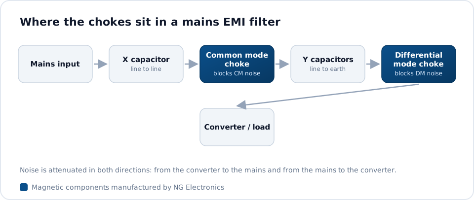
Low-power drivers commonly use a pi filter placed after the bridge rectifier: two capacitors with a small inductor between them, often a radial drum core part. This handles differential mode noise compactly. For common mode noise, a small UU-core or toroidal common mode choke is placed on the AC side, with an X capacitor across the line. Higher-power drivers use a full filter with one or two common mode stages.
The choice of inductor matters for more than attenuation. An unshielded drum inductor has an open magnetic path and can pick up or radiate stray field, so its position and orientation relative to the transformer should be tested. For the common mode stage, a compact UU part of the kind described on our common mode choke for SMPS page is typical at currents below one ampere. Where differential mode noise remains, line filter inductors can be added in series.
Constraints particular to lighting
Many luminaires are Class II, with no protective earth, so there are no Y capacitors to earth. Common mode current is instead returned to its source by a Y capacitor bridging the transformer isolation barrier, and by measures inside the transformer such as a shield winding or a cancellation winding. A capable flyback transformer manufacturer can build these in, reducing the burden on the input choke and often allowing a smaller part.
Power factor and dimming impose further limits. Capacitance on the AC side draws leading current, which lowers power factor at light load, so X capacitor values are kept modest. With phase-cut dimmers, the filter inductance and capacitance can ring when the dimmer switches, causing flicker or dimmer misfiring, and a damping resistor network is typically needed. Filter values therefore have to satisfy emissions, power factor and dimmer behaviour together.
Temperature, lifetime and component selection
Drivers are enclosed with little airflow, sometimes directly above the LED heatsink, and are expected to last for many thousands of hours. Ferrite permeability changes with temperature and falls sharply as the Curie temperature is approached, so the choke core grade should be chosen with margin above the hottest internal temperature. Copper loss in fine-wire chokes adds self-heating, which makes DC resistance as important as inductance.
Insulation deserves the same attention. The common mode choke sits directly across the mains, so winding separation, bobbin material and wire insulation class must suit both the working voltage and the temperature. Potted outdoor drivers add mechanical stress from the potting compound, which can shift the inductance of some cores. Specify the potting material and the temperature range when requesting samples, so that the part is evaluated under realistic conditions.
Standards, testing and sourcing
Lighting equipment is typically assessed against CISPR 15 and its regional equivalents, which set conducted and radiated emission requirements specific to lighting. The measurement principles are the same as for other product families, and the bench methods in our guide on how to pass conducted emissions testing apply. Test with the actual LED load, the intended cable length and the luminaire metalwork, since each changes the common mode path.
Capacitor selection interacts with every choke decision, as explained in the article on X and Y capacitors with common mode chokes. On the magnetic side, NG Electronics supplies compact UU-core chokes from 250 mA, drum core inductors from 1 µH to 1 mH, and custom parts sized to a driver housing through its EMI filter choke manufacturing service. Samples allow the filter to be proven before the driver design is frozen.
Frequently asked questions
Why do LED drivers often fail conducted emissions at low frequencies?
The switching fundamental and its first few harmonics fall in the lower part of the conducted band, and the small filter components that fit inside a driver provide limited attenuation there. Raising the differential mode inductance, adding a second capacitor to form a pi filter, or shifting the switching frequency so that fewer strong harmonics fall in band are the usual remedies.
Can I filter a Class II LED driver without an earth connection?
Yes. Without earth, Y capacitors to chassis are not available, so common mode noise is controlled with a common mode choke on the input, a Y capacitor across the isolation barrier, and transformer construction techniques such as shield windings. Keeping the capacitance between the LED board and any exposed metal low also reduces the noise current that must be handled.
What should I send to get a choke quoted for an LED driver?
Send the input voltage range, driver power, RMS input current, target inductance, available footprint and height, maximum internal temperature and whether the driver is potted. NG Electronics normally replies with a technical quotation within 24 working hours and can provide a free sample for lab approval. Custom samples are typically ready within 7 to 10 working days.
About NG Electronics
NG Electronics is a leading ISO 9001:2015 certified manufacturer of toroidal power inductors, common mode chokes, ferrite core transformers, line filter inductors, drum core inductors and custom wound magnetic components, based in Pune, India. Every part is wound and 100% electrically tested in-house. Send your LED driver input ratings and space constraints to NG Electronics at sales@ngelectronics.in to request a quotation and samples of matched chokes and inductors. Overseas enquiries are welcome.




