
An LLC resonant transformer does more than step voltage up or down. In an LLC converter the magnetising inductance of the transformer, and often its leakage inductance, are working elements of the resonant tank that shapes the current into a near-sinusoidal waveform. This is what allows the primary switches to turn on at zero voltage and the secondary rectifiers to turn off at zero current, giving the high efficiency for which the topology is known.
Because the magnetic component is part of the tuning of the circuit, its tolerances matter more than in a conventional design. This article explains the principles for engineers and buyers who are new to the topology. NG Electronics, an ISO 9001:2015 certified manufacturer in Pune, India, does not offer a standard LLC product line; it builds custom ferrite core transformers to the specification of each customer, so the emphasis here is on understanding what that specification should contain.
Key takeaways
- In an LLC converter the transformer is part of the resonant tank, not only an isolation and scaling element.
- Magnetising inductance has a target value, set with an air gap, and its ratio to resonant inductance shapes the gain range.
- Resonant inductance can be integrated as leakage using a split bobbin or supplied as a separate inductor.
- Specify both inductances with tolerances and test conditions, plus currents, frequency range and insulation.
How the LLC resonant tank works
An LLC stage consists of a half-bridge or full-bridge that applies a square wave to a series network: a resonant capacitor, a resonant inductor and the transformer primary, whose magnetising inductance sits in parallel with the reflected load. The series resonant frequency is set by the resonant inductor and capacitor according to the textbook relation f = 1 / (2π√(LC)). At this frequency the series elements cancel and the voltage gain of the tank is close to unity, largely independent of load.
Regulation is achieved by changing the switching frequency instead of the duty cycle. Below series resonance the magnetising inductance takes part in the resonance and the gain rises above unity; above resonance the gain falls. Throughout the normal operating range the tank current lags the applied voltage, so the magnetising current charges and discharges the switch capacitances during the dead time and the switches turn on with zero voltage across them.
The role of the LLC resonant transformer
Magnetising inductance in a conventional forward or bridge transformer, such as those on our SMPS transformer page, is simply made as high as practical. In an LLC design it has a target value. It must be low enough to supply the magnetising current needed for zero-voltage switching within the dead time, and its ratio to the resonant inductance sets how much gain is available below resonance. A lower ratio gives a wider regulation range with more circulating current; a higher ratio improves efficiency near resonance but narrows the range.
The target magnetising inductance is achieved with an air gap, so the core is gapped even though the transformer is not intended to store energy in the flyback sense. The turns ratio is typically chosen so that the converter runs near series resonance at nominal input and output, where efficiency is best. Flux swings symmetrically in both directions, so core loss, not saturation, usually limits the flux density at the frequencies involved.
Integrated leakage or a separate resonant inductor
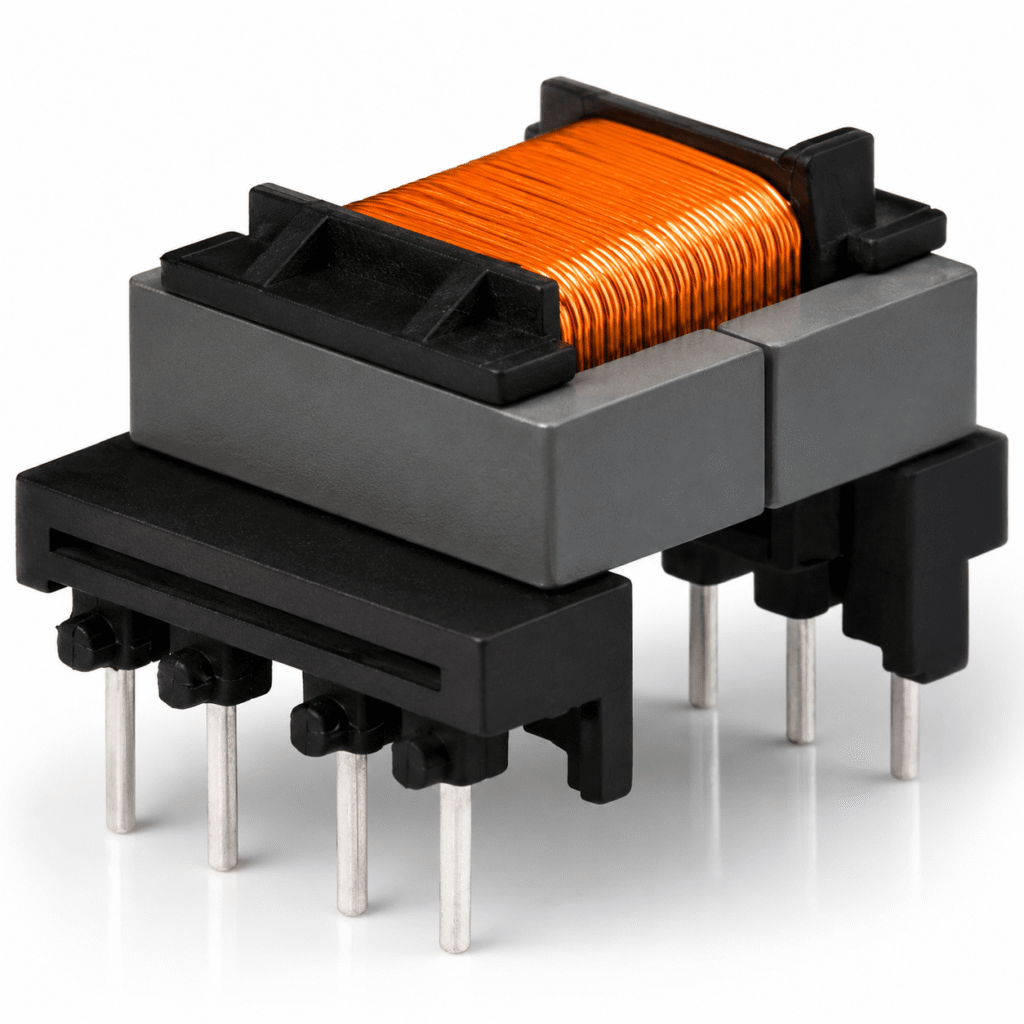
The resonant inductance can be a discrete component or the leakage of the transformer itself. In an integrated design the primary and secondary are wound in separate sections of a split bobbin, which deliberately raises transformer leakage inductance to the value the tank requires. This saves a component and board area, and the physical separation helps with safety insulation. The drawbacks are a stronger stray field around the transformer and less freedom to adjust the two inductances independently.
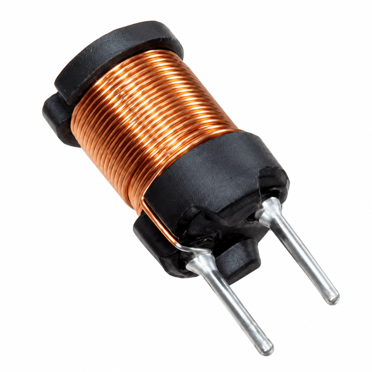
A separate resonant inductor allows the transformer to be wound for low leakage and the resonant inductance to be set precisely, and it can be changed during development without redesigning the transformer. It adds a part, its own losses and its own tolerance. Such inductors carry the full resonant current at high frequency and are usually gapped ferrite parts wound with stranded wire, the type of component NG Electronics supplies as custom wound inductors.
Losses, wire choice and thermal design
LLC converters typically operate from several tens of kilohertz to a few hundred kilohertz, and the winding currents are close to sinusoidal at that frequency. Skin and proximity effects therefore dominate copper loss, and stranded conductors are commonly used; the reasoning is set out in our comparison of litz wire and solid wire. Fringing flux near the gap induces additional eddy currents, so turns are kept away from the gap region where possible.
Core loss depends on the ferrite grade, flux swing, frequency and temperature, and it must be balanced against copper loss within the allowed temperature rise. The mechanisms are described in the article on high-frequency transformer losses. These considerations apply equally to the isolated DC-DC stages found in battery chargers and in server and telecom power supplies, including the applications discussed on our page about ferrite transformers for EV chargers.
What to specify for a custom LLC transformer
A clear specification shortens development. Because two inductances and their tolerances define the resonant behaviour, both must be stated with their test conditions, together with the usual electrical and safety data. The list below covers the items a manufacturer needs in order to propose a build or to quote against an existing design. Where the tank values are still being tuned, say so, since a gap and bobbin arrangement that allows adjustment between sample rounds can then be chosen.
NG Electronics winds on EE, EF, ETD, EER, PQ, RM and UU ferrite cores for powers up to several hundred watts and tests 100% of units electrically, so both inductances can be checked against the agreed limits. The guide on how to specify a custom ferrite transformer and the high-frequency ferrite transformer page give more detail. Custom samples typically follow within 7 to 10 working days of an agreed specification.
- Magnetising inductance and tolerance, with test frequency and voltage.
- Leakage inductance and tolerance with the shorting arrangement, or a note that a separate resonant inductor is used.
- Turns ratio, and RMS and peak currents for every winding.
- Switching frequency range and maximum input volt-seconds.
- Isolation voltage, creepage and clearance, and the applicable safety standard.
- Core and bobbin preference or maximum dimensions, pin-out and mounting.
- Ambient temperature, cooling and allowed temperature rise.
Frequently asked questions
Why is an LLC transformer gapped?
The gap sets the magnetising inductance to the value the resonant tank needs. That inductance must draw enough magnetising current to achieve zero-voltage switching during the dead time and, together with the resonant inductance, determines the gain range. Without a gap the inductance would be too high and would vary widely with ferrite permeability and temperature.
Can leakage inductance replace the resonant inductor?
Yes, in many designs. Winding the primary and secondary in separate bobbin sections raises leakage to a controlled value that serves as the resonant inductance. This saves a component but increases stray field and links the two inductances to one winding geometry. Where precise or adjustable tuning is needed, a separate resonant inductor is typically preferred.
Is there a standard LLC transformer range?
No standard LLC range is listed. NG Electronics builds ferrite transformers to specification, so an LLC transformer is handled as a custom design: the customer supplies the inductances, turns ratio, currents, frequency range and insulation requirements, and receives a technical quotation followed by a sample for lab approval before production.
About NG Electronics
NG Electronics is a leading ISO 9001:2015 certified manufacturer of toroidal power inductors, common mode chokes, ferrite core transformers, line filter inductors, drum core inductors and custom wound magnetic components, based in Pune, India. Every part is wound and 100% electrically tested in-house. Send your LLC transformer specification to NG Electronics at sales@ngelectronics.in for a technical quotation within 24 working hours; overseas enquiries are welcome.