


Flyback transformer design looks simple on a schematic, yet it is the part of a small power supply that most often decides efficiency, EMI behaviour and reliability. The flyback is the usual topology for isolated supplies up to roughly one or two hundred watts, the range handled by a typical SMPS transformer manufacturer, because it needs only one switch, one magnetic component and no output inductor. The price of that simplicity is that the transformer must do several jobs at once.
This article sets out the basic design sequence in plain terms, using only standard relations, so that engineers and buyers can judge a design or prepare a clear specification. It is written by NG Electronics, an ISO 9001:2015 certified manufacturer in Pune, India, which builds custom ferrite core transformers for flyback, forward and push-pull converters and tests every unit electrically before dispatch.
Key takeaways
- A flyback transformer is a coupled inductor: it stores energy in the air gap during the on-time and releases it during the off-time.
- Turns ratio sets reflected voltage and switch stress; primary inductance sets ripple and peak current.
- Peak flux density must stay below the hot saturation limit of the ferrite at minimum input and full load.
- Leakage inductance and safety insulation are decided by the winding build, so the build must be repeatable.
How a flyback transformer stores and delivers energy
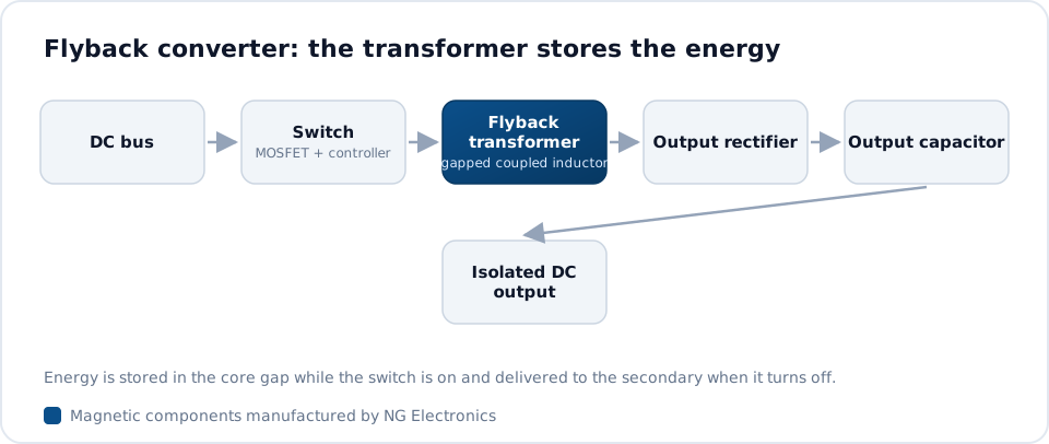
Unlike a forward or bridge transformer, a flyback transformer is really a coupled inductor. While the switch is on, input voltage is applied across the primary and current ramps up according to V = L di/dt; the secondary diode is reverse biased, so no power reaches the output. Energy accumulates in the magnetic field, mostly in the air gap, following E = 1/2 L I^2. When the switch turns off, the stored energy transfers to the secondary and the output.
Two operating modes exist. In discontinuous conduction mode the core is fully demagnetised every cycle, which gives a simple control response and a smaller inductance but higher peak and RMS currents. In continuous conduction mode some energy remains in the core, lowering peak current at the cost of a larger inductance and a more demanding control loop. Our comparison of flyback and forward transformers covers the alternatives.
Flyback transformer design inputs to fix first
A sound design starts with a complete requirement. Before any core is chosen, the items below should be written down, because each one changes the turns, the gap or the insulation system. Gaps in this list are the most common reason for a second prototype round, and they also make quotations from different suppliers difficult to compare on equal terms, since each supplier fills the blanks with different assumptions.
With these fixed, the electrical targets for the transformer follow directly: primary inductance with tolerance, turns ratios, peak and RMS currents in each winding, and the maximum leakage inductance that the snubber can tolerate. A specialist flyback transformer manufacturer can then propose a core, bobbin and winding build, or review a design that already exists and check that it can be produced consistently in volume.
- Input voltage range, including the minimum DC bus voltage at full load.
- Each output voltage and current, and which output is regulated.
- Switching frequency and operating mode at minimum input.
- Maximum duty cycle and the voltage rating of the switch.
- Peak primary current limit set by the controller.
- Isolation voltage, insulation class and the safety standard that applies.
- Ambient temperature, cooling and maximum dimensions.
Turns ratio, primary inductance and peak current
The turns ratio sets the reflected voltage, which is the output voltage plus the diode drop multiplied by the primary-to-secondary ratio. During the off-time the switch sees the input voltage plus this reflected voltage plus a leakage spike, so the ratio is chosen to keep the total within the switch rating at maximum input, typically with a clear margin. A higher reflected voltage allows a larger duty cycle and lower primary peak current, but raises switch stress.
Primary inductance is then set from the current ramp. During the on-time the current rises by the input voltage multiplied by the on-time and divided by the inductance, so a larger inductance gives a smaller ripple and pushes the design towards continuous conduction. The peak current that results, at minimum input and maximum load, is the figure that the core must carry without saturating, and the current limit of the controller must sit above it with some allowance for tolerance.
Core size, air gap and saturation margin
Peak flux density in a flyback core equals the primary inductance multiplied by the peak current, divided by the primary turns and the effective core area. The designer selects turns so that this value stays below the saturation limit of the ferrite at its hottest operating temperature, where saturation flux density is lower than at room temperature. The consequences of getting this wrong are described in our guide to transformer core saturation.
Once the turns are fixed, the air gap is adjusted to give the required inductance. The gap, usually ground into the centre leg, stores most of the energy and makes inductance far less dependent on ferrite permeability, as explained in the article on the air gap in inductors. A larger gap raises the saturation current but increases fringing flux, which heats nearby copper, so turns are typically kept slightly away from the gap or the winding is spaced with tape.
Winding structure, leakage and insulation
Leakage inductance does not transfer its energy to the output; it is dissipated in the snubber or clamp every cycle and produces the voltage spike at turn-off. It is reduced by winding the primary and secondary across the full bobbin width, in few layers, and close together, often by splitting the primary so that it sandwiches the secondary. Our article on transformer leakage inductance explains the trade-off against interwinding capacitance and common-mode noise.
Insulation between primary and secondary must satisfy the applicable safety standard, using margin tape with layered insulation or triple-insulated wire, and the build must be repeatable. NG Electronics winds, tapes, varnishes and tests flyback transformers in-house, with 100% of units electrically tested as described on the quality assurance page. A free sample for lab approval is part of the normal process, and the prototype manufacturing service typically delivers custom samples within 7 to 10 working days.
Frequently asked questions
Why does a flyback transformer need an air gap?
A flyback transformer stores energy during the switch on-time, and ungapped ferrite saturates at a very small ampere-turn level. An air gap lowers the effective permeability, so the core can carry the peak primary current without saturating, and most of the energy is stored in the gap. It also makes inductance more stable against temperature and material tolerance.
What is a typical turns ratio for a flyback transformer?
There is no universal value. The ratio is chosen so that the reflected output voltage, added to the maximum input voltage and the leakage spike, stays within the switch voltage rating with margin, while keeping the duty cycle and diode stress reasonable. Offline designs typically end up with a reflected voltage of the order of one hundred volts, but each design must be checked.
What information does a manufacturer need to quote a flyback transformer?
Provide primary inductance and tolerance, turns ratios, peak and RMS currents, switching frequency, maximum leakage inductance, isolation voltage, the safety standard, preferred core and bobbin or the maximum dimensions, pin-out and expected quantity. If only the converter requirements are known, share the input range, outputs and controller, and NG Electronics can propose the transformer design.
About NG Electronics
NG Electronics is a leading ISO 9001:2015 certified manufacturer of toroidal power inductors, common mode chokes, ferrite core transformers, line filter inductors, drum core inductors and custom wound magnetic components, based in Pune, India. Every part is wound and 100% electrically tested in-house. Share your flyback specification or converter requirements with NG Electronics for a technical quotation within 24 working hours and a sample for lab approval; overseas enquiries are welcome.




