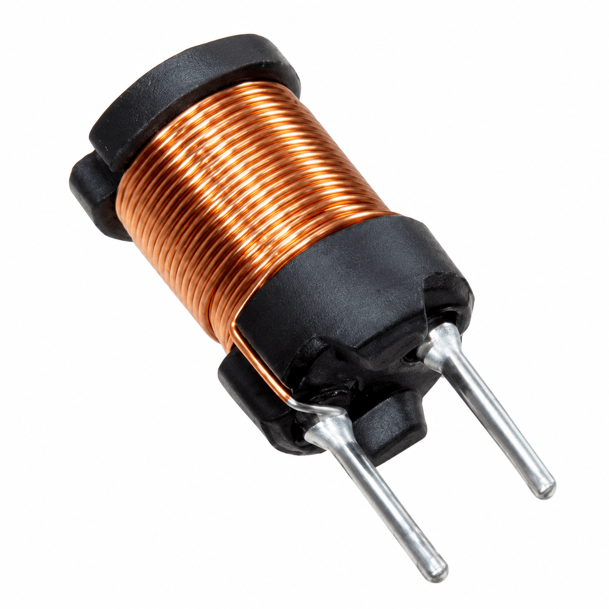

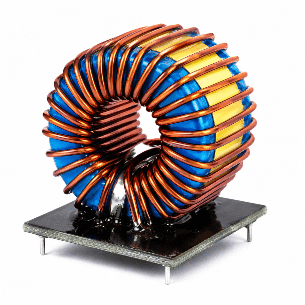
A gate drive transformer carries the switching signal, and the energy needed to charge the gate, from a ground-referenced driver to a MOSFET or IGBT whose source or emitter sits at a different, often rapidly moving, potential. It provides galvanic isolation without any floating power supply, adds very little delay and has no semiconductor junctions to age. For these reasons it remains widely used in half-bridge, full-bridge and synchronous rectifier circuits.
The component is small, but its design is constrained by a few rules that are easy to overlook, and this guide explains them one by one. It comes from NG Electronics, an ISO 9001:2015 certified manufacturer in Pune, India, whose ferrite core transformer range includes gate-drive and isolation transformers wound on toroidal, EE and RM ferrite cores and tested in-house.
Key takeaways
- A gate drive transformer delivers both signal and gate energy across an isolation barrier with no floating supply.
- The volt-second product of the longest drive pulse must stay within the rating of the core.
- Simple AC-coupled circuits are typically limited to about 50% duty cycle.
- Leakage inductance, interwinding capacitance and isolation level trade against one another in the winding build.
How a gate drive transformer works
The driver applies a voltage pulse to the primary, and the secondary reproduces it across the gate and source of the power device, scaled by the turns ratio, which is commonly 1:1. Because the secondary floats, it can follow a switch node that swings by hundreds of volts. One primary can serve two secondaries wound in opposite sense, so a single transformer can drive the two switches of a half-bridge or push-pull stage in antiphase from one driver.
A transformer cannot pass direct current. The average voltage across any winding must be zero over a cycle, otherwise magnetising current keeps rising until the core saturates. In practice a capacitor is placed in series with the primary to block the DC component of the drive signal. The result is that the pulse delivered to the gate is shifted: its positive amplitude falls as duty cycle rises, and the off-state level becomes negative.
Volt-seconds, duty cycle and saturation
The main sizing rule is the volt-second product. The flux swing in the core equals the applied voltage multiplied by the pulse duration, divided by the turns and the core cross-sectional area. The longest pulse at the highest drive voltage, which occurs at the lowest switching frequency and the largest duty cycle, must keep flux density below the limit of the ferrite with margin. The mechanism is the same as described in our article on transformer core saturation.
With simple AC coupling the usable duty cycle is typically limited to about 50%, because the gate amplitude shrinks as duty cycle grows. This suits bridge and push-pull converters, where each switch conducts for less than half the period. Wider duty ranges need a DC restoration circuit on the secondary, formed by a capacitor and diode, or a different drive method. Start-up and sudden duty changes deserve attention, since the coupling capacitor needs time to settle.
Key parameters of a gate drive transformer
A gate drive transformer is specified by a handful of parameters that pull in different directions. High magnetising inductance needs more turns, but more turns raise leakage and capacitance; strong isolation needs spacing, which also raises leakage. Knowing which parameter matters most in the application makes the compromise easier, and the list below summarises what each one controls in the finished circuit.
Leakage inductance and the gate capacitance form a resonant circuit, so excessive leakage shows up as slow edges and overshoot at the gate, usually tamed with a series gate resistor. The causes and remedies are the same as for power transformers and are covered in transformer leakage inductance explained. Interwinding capacitance matters more as switching edges become faster, because each transition injects a current pulse through it into the control side.
- Volt-second rating: the maximum pulse voltage multiplied by its duration before saturation.
- Magnetising inductance: sets magnetising current and pulse droop; higher is typically better.
- Leakage inductance: limits edge speed and rings with gate capacitance; lower is better.
- Interwinding capacitance: couples switch-node voltage transitions back to the driver; lower is better.
- Turns ratio: commonly 1:1 or 1:1:1, sometimes stepped to suit the gate voltage.
- Isolation voltage and insulation type: functional, basic or reinforced.
Core and winding construction
Gate drive transformers are usually wound on small, ungapped, high-permeability ferrite cores so that few turns give ample magnetising inductance. Toroids are popular for their low leakage and stray field; small EE, EP and RM cores with bobbins are easier to mount, give defined pin positions and suit automated assembly. The core cross-section and turns are chosen together to meet the volt-second requirement at the lowest operating frequency.
Bifilar or trifilar winding, where the wires are laid side by side, gives the lowest leakage but the highest capacitance and only wire-enamel insulation between windings. Where the secondary must be safely isolated from the control side, triple-insulated wire or separated windings with tape barriers are used, accepting more leakage. These choices are discussed further in our guide to winding configurations and insulation. The hipot test level should reflect the real working voltage across the barrier.
Specifying and sourcing a gate drive transformer
A useful enquiry states the drive voltage, frequency range, maximum duty cycle, number of secondaries, turns ratio, gate charge or peak gate current, required isolation voltage and insulation type, and the mounting style. Limits for leakage inductance and interwinding capacitance should be given where edges are fast. Applications range from bridge stages in industrial supplies to the converters described on our pages for SMPS transformers and ferrite transformers for EV chargers.
NG Electronics builds gate-drive transformers to specification, with flexible minimum order quantities of about 10 pieces for prototyping, and electrically tests 100% of units including hipot. Compact drive parts running at higher frequencies share much with the designs on the high-frequency ferrite transformer page. To discuss a requirement, use the contact page or email the specification; a technical quotation is returned within 24 working hours and overseas enquiries are welcome.
Frequently asked questions
Why does a gate drive transformer need a series capacitor?
A transformer winding cannot sustain a DC voltage. If the drive signal has a DC component, magnetising current ramps up cycle after cycle until the core saturates. A capacitor in series with the primary blocks the DC component so that the volt-seconds applied in each direction balance, at the cost of shifting the pulse levels with duty cycle.
Can a gate drive transformer work at any duty cycle?
Not on its own. With AC coupling the positive gate voltage decreases as duty cycle increases, so simple circuits are typically limited to around 50%. A DC restoration network on the secondary extends the range, but very high or rapidly changing duty cycles are usually better served by an isolated gate driver with its own floating supply.
What core is used for a gate drive transformer?
Small high-permeability ferrite cores are typical. Toroids offer low leakage inductance and low stray field, while EE, EP and RM cores with bobbins provide fixed pin positions and easier insulation barriers. The core is ungapped, and its cross-section and turns are chosen so that the largest drive pulse stays within the volt-second limit.
About NG Electronics
NG Electronics is a leading ISO 9001:2015 certified manufacturer of toroidal power inductors, common mode chokes, ferrite core transformers, line filter inductors, drum core inductors and custom wound magnetic components, based in Pune, India. Every part is wound and 100% electrically tested in-house. Email your gate drive transformer requirement to NG Electronics at sales@ngelectronics.in for a technical quotation and a sample for lab approval.