High Frequency Ferrite Transformer Supplier in India
NG Electronics · ISO 9001:2015 Certified Company
High Frequency Ferrite Transformer Supplier in India
As a high frequency ferrite transformer supplier, NG Electronics makes gate drive, isolation, forward and push-pull transformers in Pune. We are an ISO 9001:2015 certified company and test every unit electrically.
India & exportWorldwide dispatch, test certificate
Ferrite Core Transformers
A high frequency ferrite transformer supplier with in-house winding
Buyers looking for a high frequency ferrite transformer supplier usually have a converter switching somewhere between 20 kHz and 500 kHz. In that band, laminated steel is no longer practical because eddy currents in the metal turn into heat. Ferrite is a ceramic with high electrical resistivity, so those eddy currents stay small and the core remains efficient at frequencies where steel would overheat.
The price paid for low loss is a lower saturation flux density than steel, and one that falls further as the core warms up. At the lower end of the band a design is normally limited by saturation. As frequency climbs, core loss takes over as the limit, and the flux swing has to be reduced to keep the temperature rise acceptable. Doubling the frequency therefore does not halve the core size.
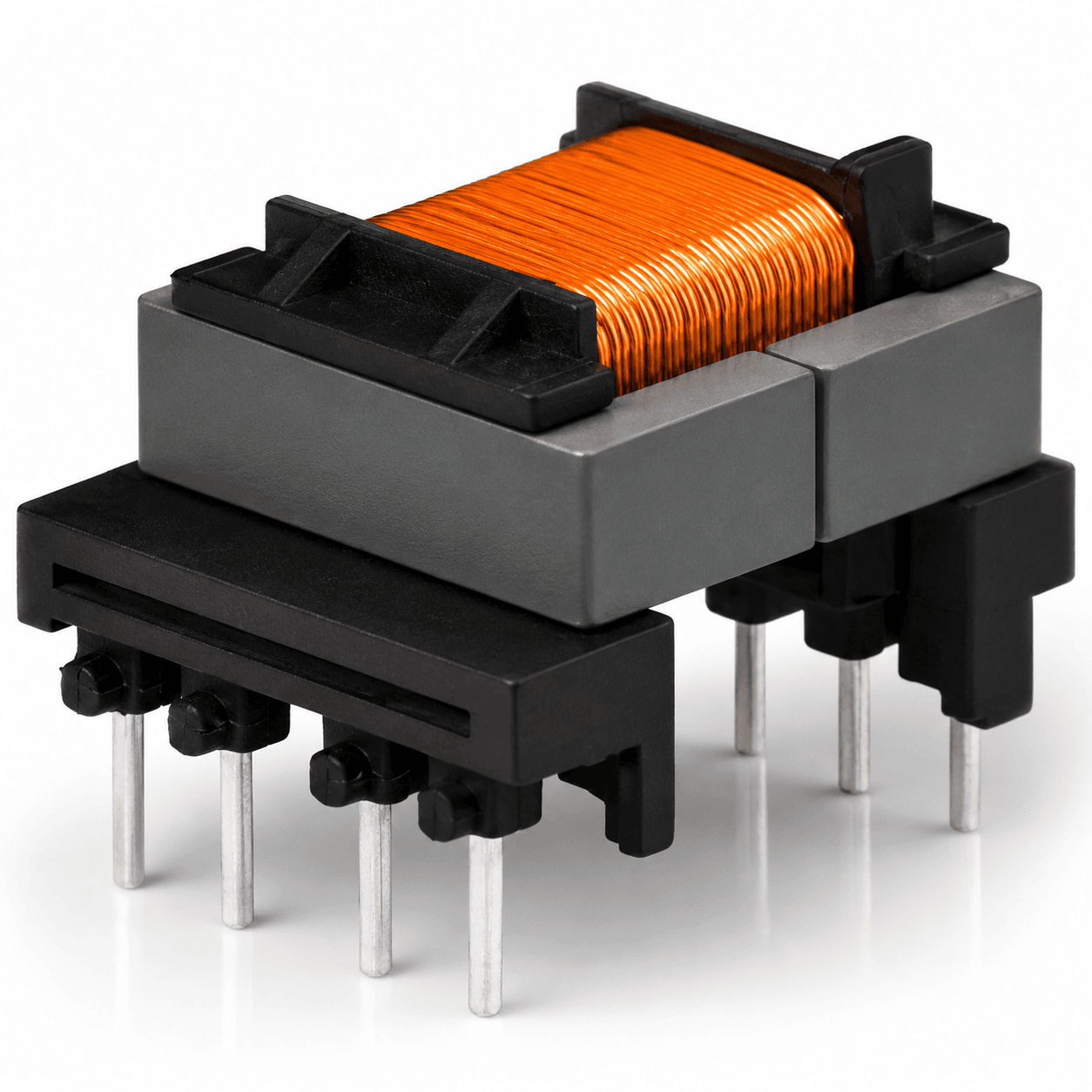
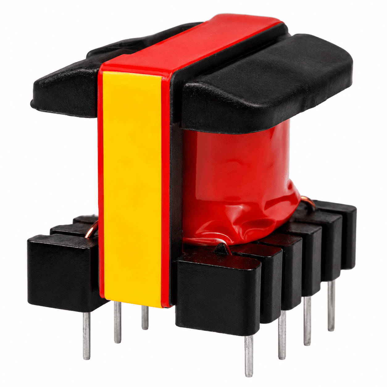
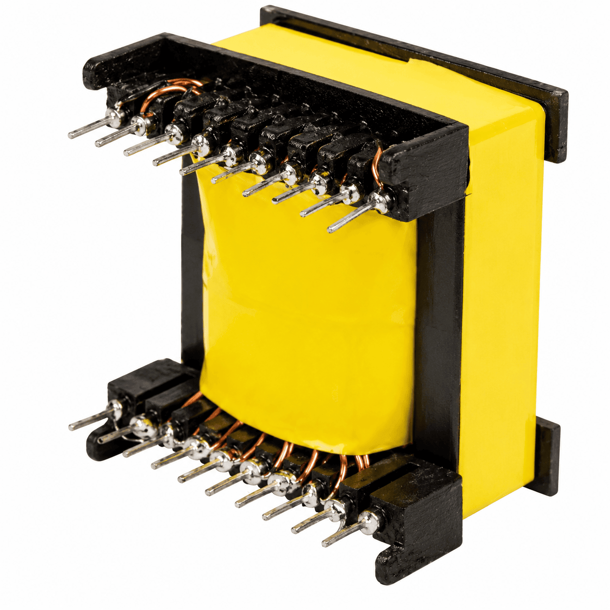
NG Electronics manufactures these parts on EE, EF, ETD, EER, UU, RM, PQ and toroidal ferrite cores, from signal-level pulse transformers under 1 VA to power transformers of several hundred watts. As a high frequency transformer manufacturer in India with winding, taping, varnishing and testing on one site, we can adjust wire type, layer order and insulation between sample rounds without waiting on outside vendors.
Ferrite cores chosen for the operating frequency and flux swing
Wire construction selected to limit AC resistance
Gate drive, isolation, forward and push-pull builds
Batch records traceable to raw material and production date
The figures below describe our manufacturing range. Loss, temperature rise and insulation values belong to the individual design and are verified on the sample you approve.
Transformer types
Gate drive, isolation, forward, push-pull, flyback and SMPS
Power range
Under 1 VA up to several hundred watts
Core material
Ferrite
Core shapes
EE, EF, ETD, EER, UU, RM, PQ and toroidal
Operating frequency
Specified per design; typically 20 kHz to 500 kHz
Wire construction
Specified per design
Isolation voltage
Specified per design; hipot tested on every unit
Testing
100% electrical testing; test certificate on request
Compliance
RoHS and REACH compliant materials; certificate copies available on request
Custom samples are typically dispatched in 7 to 10 working days. MOQ is flexible: about 10 pieces for R&D and typically 100 to 1,000 pieces for production.
Applications
High frequency transformer types we supply
Four kinds of part account for most of the enquiries we receive in this category.
Gate drive transformer
A gate drive transformer passes the drive pulse to a floating MOSFET or IGBT. It needs enough volt-second capacity to avoid saturation, low leakage for clean edges and low capacitance between windings so fast bus transitions do not disturb the gate.
Used for isolated bias supplies, sensing and communication interfaces. When an isolation transformer for high frequency use is specified, creepage, clearance and test voltage shape the bobbin and tape build as much as the turns do.
Energy passes straight through during the on-time, so the core is ungapped or nearly so and magnetising current is kept low. A reset winding or clamp returns the core flux to its starting point every cycle.
The centre-tapped primary drives the core in both directions and suits battery and low-voltage DC inputs. The two primary halves are wound together to keep them matched and to limit voltage spikes on the switches.
Send the frequency, current waveforms, isolation voltage and size limits to sales@ngelectronics.in, or call or WhatsApp +91 83290 52861 between 9am and 7pm, Monday to Saturday. Expect our technical quotation back within 24 working hours.
At high frequency, current crowds towards the surface of a conductor. The skin depth in copper is roughly 0.47 mm at 20 kHz, about 0.2 mm at 100 kHz and under 0.1 mm at 500 kHz. A solid wire much thicker than twice the skin depth carries little current in its centre, so adding copper stops reducing resistance. Several thinner insulated strands in parallel use the cross-section better.
Proximity effect is often the larger problem. The field from neighbouring turns and layers forces current into a small part of each conductor, and the loss grows quickly with the number of layers. Fewer layers, interleaved primary and secondary sections, litz wire or multi-strand wire all help. Each has a cost: litz fills the window less efficiently, and interleaving raises interwinding capacitance.
State the frequency and waveformGive the switching frequency, duty cycle range and whether the drive is unipolar or bipolar. These fix the flux swing the core must handle.
Give RMS and peak currentsWinding loss depends on RMS current and its harmonic content, so current waveforms or a simulation plot are more useful than a single DC figure.
Define isolationState the test voltage and any creepage and clearance distances required by your product standard, along with the working voltage across the barrier.
Set the thermal limitTell us the maximum ambient temperature and whether there is airflow. This decides how much core and copper loss the part can be allowed.
Limit the parasiticsIf leakage inductance or interwinding capacitance must stay below a certain value, say so at the start; both are set by the winding layout.
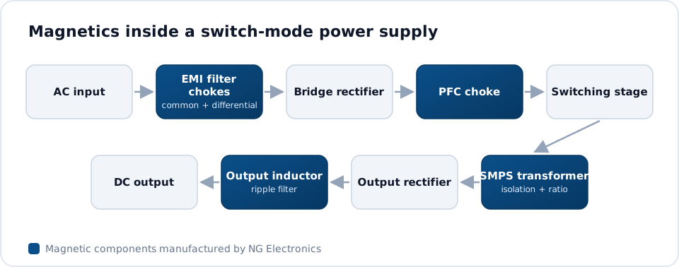
Switch mode converter block diagram with the high frequency ferrite transformer providing isolation between input and output stages.
About NG Electronics
Why NG Electronics as your high frequency transformer source
High frequency parts reward careful, repeatable winding, because a layer placed differently changes leakage and capacitance even when the turns count is right. NG Electronics is an ISO 9001:2015 certified manufacturer with a team of over 50 in Pune, and each approved design is frozen as a winding instruction that production follows lot after lot. Batch records make it possible to trace any unit back to its material and build date.
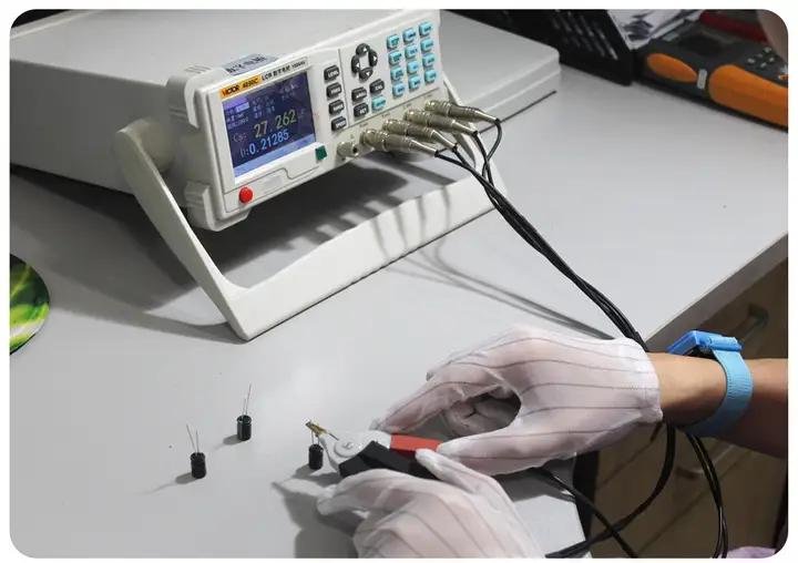
Our test bench includes LCR testers, automatic transformer testers, impulse testers, insulation breakdown testers and power analysers. For a customer sourcing a ferrite transformer for industrial power supply or drive equipment, that means inductance, winding resistance and hipot results exist for every unit shipped. The company was founded in 2017 by Nishant Gaikwad and ships across India; overseas enquiries are welcome.
ISO 9001:2015 certifiedQuality system audited and documented
Wound and tested in-houseNothing outsourced, nothing rebadged
100% electrical testingInductance, DCR, Q, saturation, hipot
Batch traceabilityRecords back to material and date
Engineer-to-engineer supportDesign help from specification to sample
India and export deliveryExport documents and test certificate
Answers about high frequency ferrite transformer supplier from NG Electronics, an ISO 9001:2015 certified company
Ferrite has high electrical resistivity, so eddy current loss in the core stays low at tens or hundreds of kilohertz, where laminated steel would run very hot. Its saturation flux density is lower than steel and drops with temperature, so designs use a modest flux swing. Different ferrite grades are optimised for different frequency bands, and the grade is chosen to suit the converter.
Most parts we build operate in converters switching between about 20 kHz and 500 kHz, which is the usual range for ferrite power transformers. The exact frequency is a design input: it determines the ferrite grade, the core size and the wire construction. Tell us your switching frequency and waveform and we will propose a suitable build.
It becomes worthwhile when the wire diameter needed for the current is much larger than twice the skin depth at the switching frequency, or when several winding layers make proximity loss significant. Stranded constructions lower AC resistance but take more window space and cost more. For low currents or lower frequencies, a single solid enamelled wire is often the better choice.
Three things: enough volt-second capacity that the core does not saturate at the longest pulse, low leakage inductance for fast rise and fall times, and low capacitance between primary and secondary so switching transients do not couple through. Because the transformer cannot pass DC, the duty cycle range of the drive circuit should be stated when you request a design.
Yes. Hipot testing is part of the electrical test carried out on all units, alongside inductance and winding resistance checks. The test voltage is taken from your specification. We use insulation breakdown testers and impulse testers, and can issue a test certificate with the order when you ask for one.
Send your specification or drawing by email or WhatsApp. We respond with a technical quotation within 24 working hours, then supply a free sample for approval in your lab, typically within 7 to 10 working days for custom parts. After approval, production runs with every unit electrically tested and delivery includes a test certificate where requested.
Tell us what you need. We reply within 24 working hours.
Send your specification or drawing for high frequency ferrite transformer supplier. NG Electronics is an ISO 9001:2015 certified company, and every enquiry is answered by our engineering and sales team in Pune.