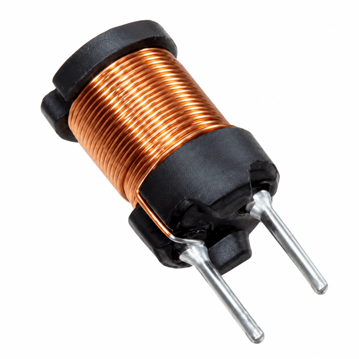

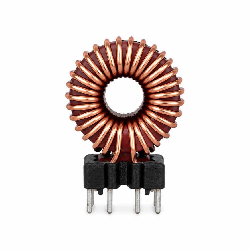
The current transformer vs power transformer comparison confuses many newcomers because the two devices look alike: both are windings on a magnetic core, and both obey the same turns-ratio laws. The difference is in how they are connected and what they are asked to do. A power transformer transfers energy from a voltage source to a load. A current transformer measures the current in a conductor and transfers almost no power at all.
That change of purpose reverses several design priorities. This educational article explains the operating principle of each, the practical differences and the points to specify. It is written by NG Electronics, an ISO 9001:2015 certified manufacturer in Pune, India. The catalogue centres on ferrite core transformers, inductors and chokes; it does not list a standard current transformer range, although custom designs can be discussed.
Key takeaways
- A power transformer is connected across a voltage source; a current transformer is connected in series with the measured circuit.
- Power transformer flux is set by applied volt-seconds; current transformer flux is set by the burden voltage.
- A current transformer secondary must never be open while primary current flows.
- Current transformers are specified by ratio, burden and accuracy; power transformers by power, voltages and efficiency.
How a power transformer operates
A power transformer has its primary connected across a voltage source. The applied voltage and its duration determine the flux in the core, the secondary voltage follows from the turns ratio, and the load decides how much current flows. Secondary load current is matched by an equal ampere-turn current in the primary, so the two cancel magnetically and the core flux stays almost independent of load. The small magnetising current that sustains the flux is an unwanted overhead.
Design priorities follow from this. The core and turns are sized so that the applied volt-seconds do not saturate the core, the conductors are sized for the RMS load current, and the aim is high efficiency, acceptable temperature rise and good voltage regulation. In switch-mode supplies the same principles apply at tens or hundreds of kilohertz using ferrite cores, the kind of part described on our SMPS transformer manufacturer page.
How a current transformer operates
A current transformer has its primary connected in series with the circuit being measured, often as a single turn formed by a conductor passing through a ring core. The primary current is imposed by the external circuit and is unaffected by the transformer. The secondary, with many turns, delivers a current equal to the primary current divided by the turns ratio into a low-value burden resistor, which converts it into a measurable voltage.
Here the core flux is set by the secondary voltage, that is, the burden voltage plus the drop in the winding resistance, and it is deliberately kept very low. Nearly all of the primary ampere-turns are cancelled by the secondary ampere-turns; only the small remainder magnetises the core, and that remainder is the measurement error. High-permeability cores, usually toroidal with evenly distributed windings, are used to keep the magnetising current and therefore the ratio and phase errors small.
Current transformer vs power transformer: side by side
With both principles in view, the contrasts become clear. The same physics is being used in opposite ways: one device is driven by voltage and built to deliver power, the other is driven by current and built to reproduce a waveform accurately. The list below sets out the points that most often matter when a component is being specified or when one type is mistakenly considered for the task of the other.
Saturation behaves differently too. A power transformer saturates when volt-seconds are excessive. A current transformer saturates when the burden voltage is too high for its core, for example with too large a burden resistor or a fault current far above its rating, and its output then collapses for part of each cycle. The underlying mechanism is covered in our article on transformer core saturation.
- Connection: primary across the source (power); primary in series with the load (current).
- What sets core flux: applied primary volt-seconds (power); secondary burden voltage (current).
- Secondary condition: may be left open safely (power); must always be closed through a burden (current).
- Design goal: efficiency and regulation (power); ratio accuracy and linearity (current).
- Rating: volt-amperes or watts and voltage ratio (power); current ratio, burden and accuracy (current).
- Typical core: sized for power throughput (power); small high-permeability ring (current).
Why a current transformer secondary must never be left open
If the secondary of an energised current transformer is opened, the primary current continues to flow because the external circuit dictates it. With no secondary current to oppose it, the whole primary current becomes magnetising current. The core is driven hard into saturation in each half-cycle, and the rapid flux reversals between can induce very high voltage peaks across the many secondary turns. These can damage insulation and present a shock hazard, and the core may overheat.
For that reason a burden, or a shorting link, must be in place before primary current flows, and protective devices are sometimes fitted across the secondary. A power transformer shows the opposite sensitivity: an open secondary is harmless, while a short-circuited secondary draws destructive current. Routine checks on any wound component, including ratio, insulation and hipot tests, are outlined in our guide to testing inductors and transformers and on the quality assurance page.
Current sensing in switch-mode supplies and what to specify
Small ferrite current transformers are widely used inside converters to sense switch or primary current with isolation and very little loss. A single-turn primary and a secondary of typically 50 to 200 turns feed a burden resistor. Because a transformer cannot pass direct current, a unidirectional pulse train requires the core to reset between pulses, usually through a diode and a reset path during the off-time, and the maximum duty cycle is limited by the time needed for that reset.
When requesting such a part, state the peak and RMS primary current, frequency, pulse width or maximum duty cycle, turns ratio, burden resistance, required accuracy and isolation voltage. NG Electronics can discuss custom sense transformers alongside its usual work as a high-frequency ferrite transformer supplier and custom toroidal inductor manufacturer, and related drive components are described in the gate drive transformer guide. Enquiries can be sent through the contact page.
Frequently asked questions
Can a power transformer be used as a current transformer?
Not effectively. A power transformer is designed for a voltage ratio and for power throughput, with magnetising current treated as a tolerable overhead. A current transformer needs very low magnetising current relative to the measured current to be accurate, which calls for a high-permeability core, a suitable turns ratio and a defined burden. Each should be used for its intended purpose.
What is the burden of a current transformer?
The burden is the impedance connected to the secondary, typically a resistor that converts the secondary current into a voltage for measurement. A higher burden gives a larger signal but raises the core flux, which increases error and brings the core closer to saturation. The burden value is therefore part of the transformer specification, not an afterthought.
Can a current transformer measure direct current?
No. A conventional current transformer responds only to changing current, because a steady flux induces no secondary voltage. A DC component in the primary also biases the core towards saturation and distorts the reading. Direct current is measured with shunt resistors or with Hall-effect and other magnetic field sensors instead.
About NG Electronics
NG Electronics is a leading ISO 9001:2015 certified manufacturer of toroidal power inductors, common mode chokes, ferrite core transformers, line filter inductors, drum core inductors and custom wound magnetic components, based in Pune, India. Every part is wound and 100% electrically tested in-house. For custom ferrite transformers, or to discuss a current-sense design, send your specification to NG Electronics at sales@ngelectronics.in; a technical quotation is returned within 24 working hours.