


Equipment that connects to a patient is held to stricter electrical safety expectations than ordinary electronics, and much of that burden falls on the power supply. Medical power supply magnetics, meaning the isolation transformer, the common mode choke and the associated inductors, largely determine how well the supply isolates the patient from the mains and how little leakage current it produces. They also influence the electrical noise that reaches sensitive measurement circuits.
This article explains the general principles of isolation and leakage as they apply to wound components, without reference to any particular approval. NG Electronics is an ISO 9001:2015 certified manufacturer in Pune, India, that builds transformers and chokes to the insulation requirements stated in the customer specification. Compliance of the finished equipment with medical standards remains the responsibility of the equipment manufacturer.
Key takeaways
- Medical supplies need greater creepage, clearance and dielectric strength than general-purpose supplies.
- Leakage limits restrict Y capacitance, so the common mode choke carries more of the filtering.
- Interwinding capacitance couples switching noise across the isolation barrier and should be specified.
- Insulation construction and leakage inductance pull in opposite directions and must be balanced.
Why medical power supply magnetics are different
Medical electrical equipment is generally designed with reference to IEC 60601-1, which defines means of protection for operators and for patients and sets limits on leakage currents. The practical consequences for a supply are larger creepage and clearance distances, higher dielectric test voltages and, in many cases, two independent layers of protection between mains and output. The exact figures depend on working voltage and the classification of the applied part, and must be taken from the standard itself.
A second difference is the leakage budget. In an ordinary supply, generous Y capacitors between primary and earth make EMI filtering easy. In medical equipment the current those capacitors pass to earth is tightly restricted, so their value must be small. The filter then has to rely more heavily on inductance, and the transformer must contribute as little noise as possible in the first place.
Isolation transformer construction
The transformer is the main barrier. Reinforced or double insulation between primary and secondary can be achieved with margin tape and multiple layers of insulating tape, with triple-insulated winding wire, or with a sectioned bobbin that separates the windings physically. Each method trades winding space against leakage inductance, and each has consequences for cost and size. The options are compared in transformer winding configurations and insulation.
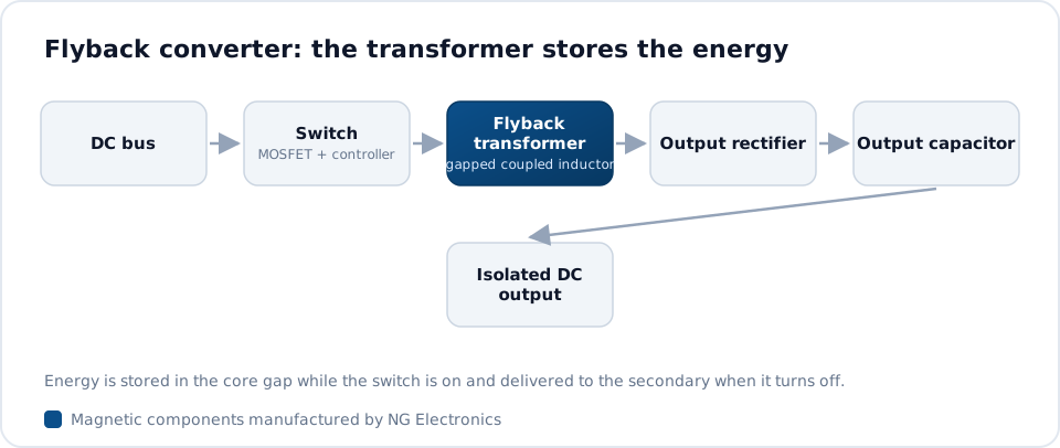
Greater separation between windings increases leakage inductance, which raises the voltage spike on the switch in a flyback and affects regulation; the effect is explained in transformer leakage inductance explained. The designer therefore specifies both the insulation system and an upper limit on leakage inductance, and the manufacturer arranges the windings to satisfy both. Ferrite core transformers from NG Electronics are wound, taped, varnished and hipot tested in-house.
Interwinding capacitance and leakage current
Every transformer has capacitance between its primary and secondary windings. The switching voltage on the primary drives a displacement current through this capacitance to the secondary, where it appears as common mode noise and adds to the leakage current that can flow to the patient side. Reducing the facing area of the windings, increasing their spacing or using a sectioned bobbin lowers the capacitance, though usually with some increase in leakage inductance.
An electrostatic shield, a single open turn of foil connected to a quiet point on the primary, diverts much of this current back to its source. Winding order also matters: placing the end of the primary that has the least voltage swing next to the secondary reduces the noise injected. These details should be fixed on the drawing, because small changes in construction alter the capacitance and the emission results. The high-frequency ferrite transformer page lists the constructions available.
Common mode chokes when Y capacitance is limited
With small Y capacitors, the common mode choke carries most of the filtering duty. Higher inductance and a wider effective frequency range are needed, which points to high-permeability MnZn ferrite or nanocrystalline cores and sometimes to two chokes in series, each covering a different band. The interaction between choke and capacitors is described in X and Y capacitors with common mode chokes.
Winding capacitance limits high-frequency performance, so sectional winding with a clear gap between the two halves is typical, and it also provides the creepage between line and neutral windings. The NG Electronics range of common mode chokes spans 1 mH to 100 mH and 250 mA to 50 A, and selection for switching supplies is covered on the common mode choke for SMPS page.
Testing, documentation and specification
Because safety depends on insulation, routine dielectric testing of every transformer is essential, and the test voltage and duration should be stated in the specification. Inductance, leakage inductance, turns ratio and DC resistance are checked at the same time. At NG Electronics all units are electrically tested, batch records give traceability to raw material and production date, and the procedures are summarised on the quality assurance page.
A useful enquiry includes the topology, power level, input range, required insulation type between each pair of windings, test voltages, creepage and clearance targets, maximum interwinding capacitance and any shield requirement. Material declarations are often requested as well; RoHS and REACH compliant materials are used, and certificate copies are available on request. The SMPS transformer page shows the core families that can be offered.
- Insulation type required between each pair of windings
- Dielectric test voltage and duration
- Maximum leakage inductance and interwinding capacitance
- Shield winding requirement and its connection point
Frequently asked questions
Why is leakage current so important in medical power supplies?
A patient may be connected to the equipment through electrodes or probes, sometimes with reduced skin resistance, so even small currents matter. Standards for medical electrical equipment therefore set much lower leakage limits than those for general equipment. The transformer capacitance and the Y capacitors are the main paths, which is why both are kept small.
How does an electrostatic shield in a transformer help?
A shield is a single open turn of foil placed between primary and secondary and tied to a quiet primary node. Displacement current that would otherwise couple through the interwinding capacitance to the secondary flows into the shield and returns to the primary instead. This lowers common mode noise at the output and eases EMI filtering.
Are these transformers and chokes certified for medical use?
No medical approvals are claimed for the components. They are manufactured under an ISO 9001:2015 quality system to the insulation, creepage and test requirements given in the customer specification, and every unit is hipot tested. Certification of the finished medical equipment is carried out by the equipment manufacturer with its chosen test laboratory.
About NG Electronics
NG Electronics is a leading ISO 9001:2015 certified manufacturer of toroidal power inductors, common mode chokes, ferrite core transformers, line filter inductors, drum core inductors and custom wound magnetic components, based in Pune, India. Every part is wound and 100% electrically tested in-house. Send your transformer or choke specification, including insulation and test voltage requirements, to NG Electronics at sales@ngelectronics.in for a technical quotation, typically within 24 working hours.




