

Telecom equipment is expected to run without interruption for years, often in roadside cabinets and on masts where maintenance is costly. Telecom power supply magnetics are central to that reliability. From the rectifier that converts mains to the nominal 48 V bus, through isolated bus converters, to the point-of-load regulators beside each processor, every stage depends on a transformer or an inductor that must be efficient, compact and predictable across temperature.
This article maps the magnetic components in a typical telecom power chain and explains the properties that matter in each. NG Electronics is an ISO 9001:2015 certified manufacturer in Pune, India, that winds and tests ferrite transformers, power inductors and common mode chokes in-house. Design teams outside India are welcome to send their specifications, and test certificates are supplied with orders on request.
Key takeaways
- Telecom power passes through several conversion stages in series, so each magnetic loss is multiplied.
- LLC rectifier transformers need controlled magnetising and leakage inductance.
- Low DCR is critical for bus converter and point-of-load inductors at low voltage.
- Common mode chokes are needed on AC inputs, 48 V feeds and signal lines.
The telecom power chain
Most network sites distribute power at a nominal 48 V DC, historically with the positive conductor earthed, because that voltage can be backed up directly by battery strings. Rectifier modules convert AC mains to this bus and share load in parallel for redundancy. Inside the equipment, isolated DC-DC converters step the bus down to an intermediate rail, and non-isolated buck converters then produce the low voltages required by processors, memory and radio circuits.
The result is a chain of three or four conversion stages in series, so the efficiency of each multiplies. A small loss in a transformer or inductor is repeated at every stage and must be removed as heat from a sealed or fan-cooled enclosure. This is why telecom designers pay close attention to core material, winding resistance and operating frequency, and why component consistency from batch to batch is treated as a design requirement.
Telecom power supply magnetics in the rectifier
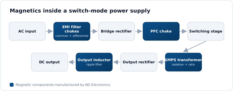
A rectifier module generally contains a power factor correction stage followed by an isolated converter, very often an LLC resonant design chosen for its soft switching and high efficiency. The PFC choke carries line-frequency current with high-frequency ripple and is typically built on a powder core or gapped ferrite. Its inductance must hold up at the peak current reached at minimum line voltage. A suitable starting point is described on the toroidal inductor for SMPS page.
The LLC transformer has a defined magnetising inductance and a controlled leakage inductance, since both take part in the resonant tank; the reasoning is covered in LLC resonant transformer basics. Safety insulation between primary and secondary is required because the output is accessible to service staff. NG Electronics manufactures ferrite core transformers from under 1 VA up to several hundred watts, and the SMPS transformer page sets out the core shapes offered.
Bus converters and point-of-load inductors
Isolated bus converters operate at high frequency with planar or conventional wound transformers in forward, half-bridge or full-bridge arrangements. Their output inductors carry substantial current at low voltage, so DCR is critical: at these voltage levels a few milliohms represent a noticeable share of the loss. Flat or multi-strand conductors and short winding lengths help, and the core must hold inductance at the peak of the ripple.
Point-of-load buck converters use small inductors placed close to the load. Ripple follows from the voltage across the inductor, the duty cycle, the inductance and the frequency, and designers typically choose a ripple of 20 to 40 per cent of load current. Shielded parts limit coupling into sensitive radio and clock circuits. Drum core inductors from 1 µH to 1 mH are available in shielded and unshielded SMD and radial forms, with tape and reel where required.
EMI control on power and signal lines
Telecom equipment shares cabinets with sensitive receivers, so emission limits are strict; information technology and multimedia equipment is commonly assessed against CISPR 32. Common mode chokes are fitted at the AC input, on the 48 V feed and frequently on data and signal pairs. Each needs enough impedance in the problem frequency band without saturating under the direct current it carries, and without degrading the wanted signal on data lines.
On power inputs, a high-permeability MnZn ferrite or nanocrystalline toroid with sectional or bifilar winding is typical. The NG Electronics range of common mode chokes runs from 250 mA to 50 A, and guidance on matching a choke to a converter is given on the common mode choke for SMPS page. A practical route through the compliance process is described in how to pass conducted emissions testing.
Environment, lifetime and supply continuity
Outdoor radio units and cabinets see wide temperature swings, humidity and, in some regions, salt or dust. Magnetics for these products need insulation systems and finishes suited to the conditions, and varnish impregnation is commonly specified to hold windings firmly and keep moisture out. Thermal design should consider the highest ambient together with solar heating of the enclosure, because natural convection is often the only cooling available.
Network equipment stays in production and in service for a long time, so buyers value stable part numbers, traceable batches and documented testing. Every unit is electrically tested for inductance, DCR and hipot before dispatch, and batch records link each lot to raw material and production date. Higher-density architectures are pushing similar requirements into computing, as discussed in data centre power supply magnetics.
- Input and output voltage ranges, power and topology for each stage
- Inductance, leakage inductance and their tolerances
- Insulation requirement, test voltage and creepage
- Ambient range, cooling and any impregnation or finish requirement
Frequently asked questions
Why is 48 V used for telecom power distribution?
A nominal 48 V bus can be supported directly by battery strings, which gives simple and dependable backup. The voltage is low enough to be treated as safe to touch under most safety frameworks, yet high enough to keep distribution currents and cable sizes manageable. The convention is long established, so equipment from many suppliers is compatible.
What matters most in a point-of-load inductor?
Low DCR, an adequate saturation current and a small footprint are the main requirements. At low output voltages, resistive loss in the inductor is a meaningful part of total loss. Shielded construction is typically preferred near radio and clock circuits, and inductance should be confirmed at peak current and at the highest board temperature.
Can transformers and chokes be customised for a telecom rectifier?
Yes. Transformers can be wound on EE, EF, ETD, EER, RM, PQ and toroidal ferrite cores to a specified inductance, leakage inductance and insulation system, and chokes can be built on ferrite or nanocrystalline cores. A free sample is supplied for lab approval before production, and test certificates are available with orders on request.
About NG Electronics
NG Electronics is a leading ISO 9001:2015 certified manufacturer of toroidal power inductors, common mode chokes, ferrite core transformers, line filter inductors, drum core inductors and custom wound magnetic components, based in Pune, India. Every part is wound and 100% electrically tested in-house. Send your telecom power supply specification to NG Electronics at sales@ngelectronics.in for a technical quotation, typically within 24 working hours, and samples for lab approval.




