


GaN and SiC magnetics is shorthand for a practical question that many power designers now face: when the transistors change, what has to change in the inductors and transformers around them? Gallium nitride and silicon carbide switches turn on and off far faster than conventional silicon devices and tolerate higher switching frequencies with lower switching loss. That shifts the limits of a converter away from the semiconductor and towards the wound components, which now decide much of the size, efficiency and electromagnetic behaviour of the finished product.
This article explains, in engineering terms, how wide-bandgap devices alter the requirements for core materials, windings, insulation and filtering. Some parts become smaller, some become harder to design, and nearly all need closer attention to losses and parasitics. The aim is to help you write a better specification, whether you buy a standard part from a catalogue or commission a custom one.
Key takeaways
- Higher switching frequency lowers the inductance needed, but core and winding losses rise.
- Designs typically become limited by temperature rise instead of saturation.
- Fast edges make winding capacitance and common-mode noise first-order concerns.
- A specification built around a loss budget gives better results than one built around a core size.
Why wide-bandgap switches rewrite the magnetics brief
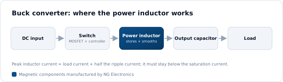
In a buck stage the inductor ripple current follows the standard relation ripple = V x D / (L x f). If the switching frequency f rises and the designer keeps the same ripple, the required inductance L falls in proportion. Less inductance means fewer turns or a smaller core, and the stored energy, E = 1/2 L I^2, falls too. This is the main reason wide-bandgap converters are associated with compact magnetics: the semiconductor finally allows frequencies at which smaller cores become usable.
The saving is not automatic. Core loss per unit volume climbs steeply with frequency, and winding resistance rises through skin and proximity effects. A design that was limited by saturation at a low frequency typically becomes limited by temperature rise at a high one. Engineers therefore often settle on a frequency well below what the transistor could manage, because the magnetic component sets the practical optimum. The article on how core losses arise in inductors covers the underlying mechanisms.
Core materials for GaN and SiC magnetics
Ferrite remains the usual choice for transformers and resonant inductors at high frequency because its resistivity keeps eddy-current loss low. Material grade matters more than before: ferrite makers offer grades intended for different frequency bands, and a grade that performs well at a modest frequency can run hot when pushed several times higher. Designers typically reduce the peak flux swing as frequency increases, so the core is used well below its saturation limit and sized by loss.
For inductors that carry a large DC bias, such as boost and output chokes, distributed-gap powder cores including iron powder, Sendust, MPP and High Flux are still relevant, as they saturate gradually and avoid the fringing losses of a single discrete gap. Their core loss is higher than that of ferrite, so the choice depends on the ratio of ripple to DC current. NG Electronics winds toroidal power inductors on both iron powder and ferrite cores, with the material selected against the actual ripple, frequency and ambient temperature.
Windings: skin effect, proximity effect and litz wire
At higher frequencies current crowds towards the surface of a conductor, and neighbouring turns push it into even smaller regions. The result is an AC resistance that can be many times the DC value if the winding is laid out without care. Common countermeasures are multi-strand or litz conductors, foil windings, fewer layers, and interleaving primary and secondary sections in a transformer. Each has a cost: litz wire fills the window less well, and interleaving raises interwinding capacitance.
The correct conductor depends on the ripple content. A choke carrying mostly DC with a small ripple component may be best served by solid wire with low DC resistance, while a resonant transformer carrying nearly pure AC benefits from fine stranding. The comparison of litz wire and solid wire in magnetics sets out when each makes sense. For isolated stages, a high-frequency ferrite transformer built to your winding arrangement lets you control leakage inductance and AC resistance together.
Fast edges, parasitic capacitance and EMI
Wide-bandgap devices switch with very high dv/dt and di/dt. Every picofarad between windings, or between a winding and the core, conducts a displacement current on each edge, and that current returns through the chassis as common-mode noise. Winding capacitance also lowers the self-resonant frequency, above which the part no longer behaves as an inductor. Single-layer windings, sectioned bobbins, spacing between start and finish turns and shield windings are the usual tools for keeping capacitance down.
Because the noise spectrum extends further up in frequency, the input filter often needs rethinking. Common mode chokes may need core materials that hold their impedance across a wider band, and low-capacitance winding styles become more valuable. If the filter is being revised for a faster converter, an EMI filter choke manufacturer can adjust turns, core material and winding separation to suit the emissions that were measured on the prototype.
Thermal density, insulation and resonant topologies
A smaller component has less surface area from which to lose heat, so loss density becomes the governing constraint, and the cooling conditions must be stated clearly. Silicon carbide is typically used at higher bus voltages, in equipment such as EV chargers and solar inverters, where creepage, clearance and hipot level deserve as much attention as loss. Many of these converters use soft-switching stages, described in LLC resonant transformer basics, in which leakage inductance is a designed parameter. A ferrite transformer for an EV charger is a typical case where isolation and controlled leakage are specified together.
Specifying magnetics for a wide-bandgap design
Catalogue parts are usually characterised at modest frequencies, so a wide-bandgap project often ends with a custom component. A useful specification states the topology, switching frequency range, inductance and tolerance, DC and ripple current, peak current, permitted temperature rise, ambient and cooling, isolation voltage, and any limit on winding capacitance or leakage inductance. Stating the loss budget is more helpful than stating a core size.
NG Electronics is an ISO 9001:2015 certified manufacturer in Pune, India, producing custom wound inductors on ferrite, iron powder, MPP, Sendust, High Flux, nanocrystalline and air cores. Parts are wound and tested in-house, with every unit electrically tested for inductance, DCR, Q factor, saturation current and hipot. Custom samples are typically ready within 7 to 10 working days, which suits high-frequency design, where the first prototype usually reveals what the second should change. Overseas enquiries are welcome.
Frequently asked questions
Do GaN and SiC devices always make inductors smaller?
Not always. Higher switching frequency reduces the inductance needed for a given ripple, which allows a smaller core. However, core loss and AC winding resistance increase with frequency, and a smaller part has less surface area to shed heat. The final size is typically set by temperature rise, so the reduction is real but smaller than a simple frequency ratio would suggest.
Which core material suits high-frequency wide-bandgap converters?
Low-loss power ferrite is the usual choice for transformers and resonant inductors, with the grade matched to the operating frequency band. Inductors with a large DC bias often use powder cores such as Sendust, MPP or High Flux for their gradual saturation. Nanocrystalline cores are common in common mode chokes. The right answer depends on ripple, bias and temperature.
Can custom magnetics be built for a GaN or SiC design?
Yes. NG Electronics builds custom inductors and ferrite transformers to the customer's specification, including switching frequency, current, insulation and winding arrangement. Share the electrical requirements and a technical quotation typically follows within 24 working hours. A sample is supplied for laboratory approval before production, and each production unit is electrically tested.
About NG Electronics
NG Electronics is a leading ISO 9001:2015 certified manufacturer of toroidal power inductors, common mode chokes, ferrite core transformers, line filter inductors, drum core inductors and custom wound magnetic components, based in Pune, India. Every part is wound and 100% electrically tested in-house. Send your switching frequency, current and insulation requirements to NG Electronics for a technical quotation and a sample built to your wide-bandgap design.




