

A charging station is, at its core, a high-power switch-mode converter that must draw clean current from the grid and deliver tightly controlled direct current to a battery. Magnetics for EV chargers make that possible: they filter noise at the mains input, shape the input current in the power factor correction stage, carry power across the isolation barrier and smooth the output. In a DC fast charger they also account for a significant share of the weight, volume and loss.
This guide follows the power path from the AC inlet to the vehicle connector and explains what each wound component has to achieve. It covers off-board chargers and charging modules rather than vehicle-mounted electronics. NG Electronics is an ISO 9001:2015 certified manufacturer in Pune, India, producing chokes, inductors and ferrite transformers that are wound and tested in-house, and enquiries from overseas design teams are welcome.
Key takeaways
- A charger module contains an EMI filter, a PFC stage, an isolated DC-DC converter and an output filter, each with its own magnetics.
- Three-phase common mode chokes are magnetised only by the noise current, not by the load current.
- Resonant converters need controlled leakage and magnetising inductance, so tolerances belong on the drawing.
- Assess every part at maximum ambient with the real cooling arrangement.
Where magnetics for EV chargers sit in the power path
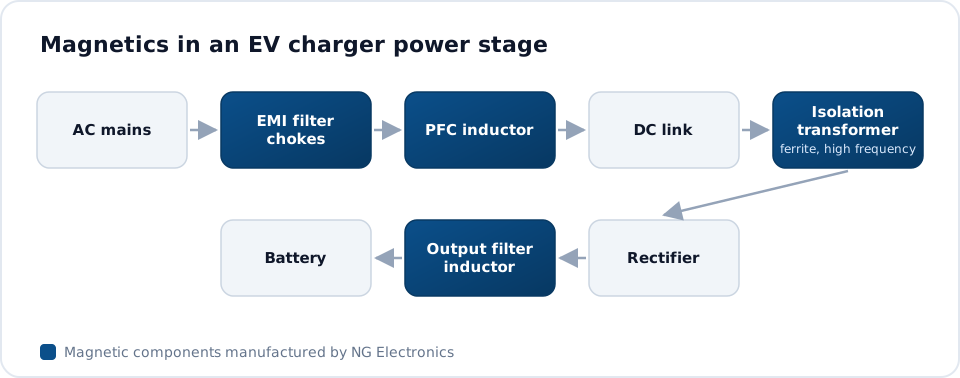
Most DC chargers are built from modular power units connected in parallel, each rated at some tens of kilowatts. Within a module the sequence is broadly the same: a three-phase EMI filter, an active rectifier that provides power factor correction, a DC link, an isolated DC-DC converter and an output filter. Auxiliary supplies and isolated gate-drive circuits surround these stages. AC wallboxes are simpler, since the conversion happens inside the vehicle, but they still contain small supplies and filtering.
Each stage uses a different kind of magnetic part. Filter chokes need high impedance to noise with low loss at mains frequency. PFC inductors need stable inductance under heavy current. The isolation transformer needs low loss at high frequency together with a robust insulation system. Treating these as separate design problems usually gives a better result than trying to reuse one core family everywhere.
Three-phase EMI filtering at the input
Fast-switching devices create both differential and common mode noise that would otherwise travel back into the supply network. The input filter typically combines one or two stages of three-phase common mode choke with X and Y capacitors and, where needed, separate differential mode inductors. The three phase windings share one core, so the load currents cancel magnetically and only the common mode component magnetises the material, as described in our introduction to three-phase EMI filter basics.
Core material is chosen for impedance across the frequency range where the emissions peak. Nanocrystalline cores provide high permeability and good thermal stability in a small volume, which suits high-current modules, while MnZn ferrite remains a sound choice for lower ratings. NG Electronics supplies common mode chokes up to 50 A in ring-core form, and the high-current common mode choke page describes the three-phase constructions in more detail.
PFC and boost inductors
The active front end forces the input current to follow the voltage waveform, and its inductors set the ripple that the EMI filter must then remove. Three-phase chargers commonly use a Vienna rectifier or a six-switch active front end, each with one inductor per phase. Ripple is governed by V = L di/dt, so a higher switching frequency permits lower inductance, although core loss and winding loss at the ripple frequency then need closer attention.
Powder cores such as Sendust and High Flux tolerate large current peaks because their inductance falls gradually, whereas gapped ferrite offers lower loss when the ripple component is large. Designers typically specify inductance at both zero current and peak current so that the roll-off is controlled. The principles are the same as in single-phase supplies and are set out in our guide to PFC choke design and selection. Non-standard ratings are handled as custom wound inductors.
The isolation transformer and resonant inductor
Galvanic isolation between the grid and the vehicle battery is provided by a high-frequency transformer, usually within an LLC resonant converter or a phase-shifted full bridge. In an LLC stage the leakage inductance, or a separate resonant inductor, forms part of the tank circuit together with the magnetising inductance, so both values must be held within a defined tolerance. Background on this topology is available in LLC resonant transformer basics.
At these frequencies skin and proximity effects dominate copper loss, so litz wire or foil windings are typical, and the core is a low-loss power ferrite in a PQ, ETD or EE shape. Insulation between primary and secondary must match the working voltage and the safety standard the charger is designed to, and every transformer should be hipot tested. Design considerations for this part are collected on the ferrite transformer for EV charger page.
Auxiliary supplies, gate drives and output filtering
Control boards, contactors, fans and communication circuits are fed from auxiliary converters, most often flyback designs running from the DC link or from the mains. Isolated gate drivers for the power switches need their own small transformers or isolated supplies with low interwinding capacitance, so that fast voltage edges do not inject current into the control side. These small parts determine whether the charger starts and stays running.
At the output, a filter inductor and capacitor reduce the ripple delivered to the battery, and a further common mode stage limits noise on the charging cable. The NG Electronics range of ferrite core transformers runs from under 1 VA up to several hundred watts, which covers auxiliary, gate-drive and lower-power isolated stages, and the high-frequency ferrite transformer page lists the core shapes offered.
Thermal design and specification
Chargers work outdoors, often at full power for long periods, and many are sealed against dust and moisture. The magnetics therefore need to be assessed at the maximum ambient with the actual cooling arrangement, whether forced air or a liquid-cooled plate. Copper loss rises with temperature, and ferrite loss has a minimum at a material-specific temperature, so a design that looks comfortable at room temperature may behave differently when hot.
A clear specification shortens development and reduces the number of sample iterations, and the items below are worth stating for each part along with the mechanical envelope and mounting method. No automotive qualification is implied by any of this: the requirements of the end equipment remain the responsibility of the charger manufacturer, and each component is built and tested to the agreed drawing.
- Inductance at zero current and at peak current, with tolerance
- RMS and peak current, ripple amplitude and switching frequency
- Insulation type, test voltage, creepage and clearance
- Maximum ambient temperature and cooling method
Frequently asked questions
Which magnetic components does a DC fast charger module contain?
A typical module has three-phase common mode chokes and differential inductors in the input filter, one PFC inductor per phase in the active rectifier, a high-frequency isolation transformer with a resonant or output inductor in the DC-DC stage, and an output common mode choke. Small flyback and gate-drive transformers support the control electronics.
Why is nanocrystalline material often used for charger EMI chokes?
Nanocrystalline alloys combine high permeability with a high saturation flux density and stable behaviour over temperature. For a given impedance this typically allows fewer turns or a smaller core than MnZn ferrite, which reduces copper loss at high current. Ferrite remains suitable for lower currents and where cost is the main constraint.
Does NG Electronics hold automotive approvals for these parts?
No automotive approvals are claimed. Parts are manufactured under an ISO 9001:2015 quality system, built to the customer drawing and 100 per cent electrically tested for inductance, DCR, saturation current and hipot. RoHS and REACH compliant materials are used, and certificate copies and test certificates are available on request.
About NG Electronics
NG Electronics is a leading ISO 9001:2015 certified manufacturer of toroidal power inductors, common mode chokes, ferrite core transformers, line filter inductors, drum core inductors and custom wound magnetic components, based in Pune, India. Every part is wound and 100% electrically tested in-house. Share your charger magnetics specification with NG Electronics at sales@ngelectronics.in to receive a technical quotation, typically within 24 working hours, and a sample for evaluation.




