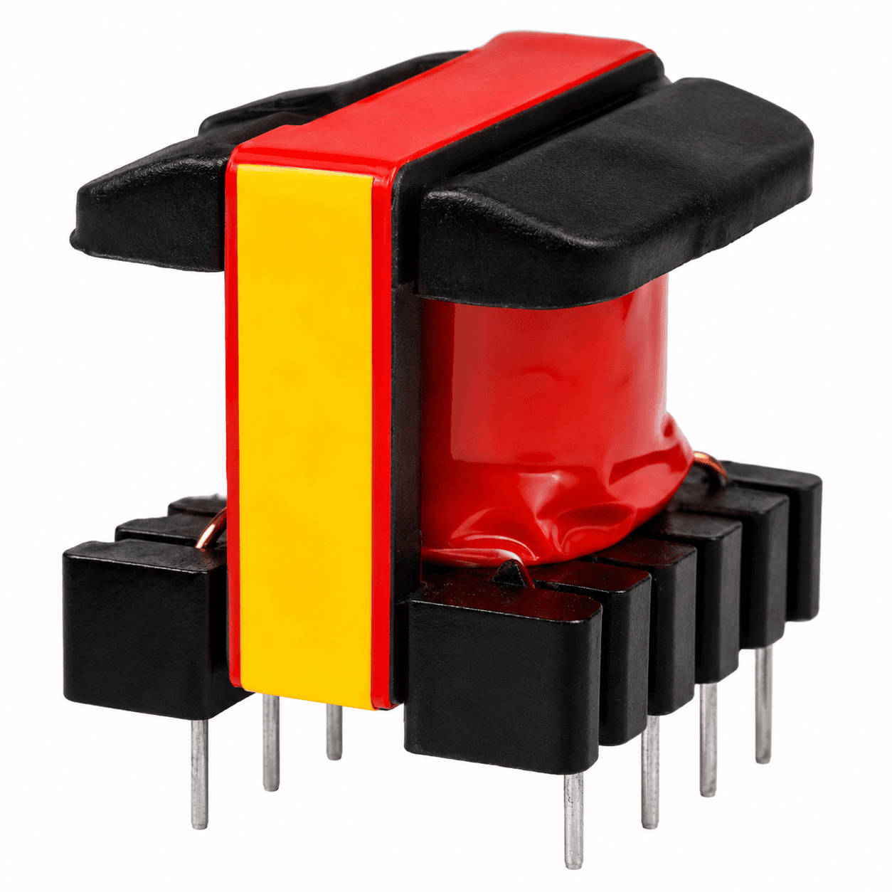
Mains-input flyback transformers
Splitting the primary around the secondary keeps leakage inductance low, so the clamp dissipates less. Margin tape or triple-insulated wire maintains the spacing between mains and output sides.
Enquire now


NG Electronics · ISO 9001:2015 Certified Company
How the copper is arranged decides leakage inductance, losses and safety margin. NG Electronics, an ISO 9001:2015 certified manufacturer in Pune, explains the winding and insulation choices in ferrite transformers.
Transformer winding configurations and insulation are decided together, because every layer of tape and every millimetre of margin takes space away from copper. Two transformers with identical turns on the same core can behave very differently: one runs cool with a small leakage spike, the other overheats and rings. The difference lies in the order of the windings, how each layer is filled, and what separates primary from secondary.
The simplest arrangement puts the whole primary on the bobbin first and the secondary on top. It is easy to wind and insulate, but the magnetic field between the two windings is at its strongest, so leakage inductance and proximity loss are highest. An interleaved winding splits one winding around the other, typically half the primary, then the secondary, then the remaining primary. This roughly halves the peak field and cuts leakage inductance considerably, at the cost of more insulation barriers and higher capacitance between primary and secondary.
Other transformer winding techniques solve specific problems. Bifilar winding lays two wires side by side for very tight coupling, which suits gate-drive transformers and centre-tapped push-pull primaries, but the wire enamel then carries the voltage between them. Multi-strand or litz wire reduces skin and proximity loss at high frequency. Spreading a low-turn winding evenly across the full bobbin width improves its coupling to the layers beside it.
 ISO 9001:2015 certified
What each term on a transformer drawing means and when to use it.
| Layer winding | Turns laid side by side in full layers. Fill each layer across the bobbin width for good coupling. |
|---|---|
| Interleaved winding | One winding split around another, such as P-S-P. Lowers leakage inductance and proximity loss. |
| Bifilar winding | Two wires wound together as a pair. Used where coupling matters more than isolation. |
| Multi-strand and litz wire | Several thin insulated strands in parallel. Chosen when skin depth is smaller than the wire radius. |
| Interlayer tape | Insulating tape between layers and windings. Provides isolation and a flat surface for the next layer. |
| Margin tape | Tape strips at the bobbin edges that keep windings away from the flange to build creepage distance. |
| Triple-insulated wire | Wire with three insulation layers, allowing full-width winding without margins where the standard permits. |
| Shield winding | A single-layer winding or foil tied to a quiet node between primary and secondary to reduce common-mode noise. |
| Varnish impregnation | Fills gaps, locks turns mechanically and improves moisture resistance and heat transfer. |
Actual insulation build, test voltage and distances are specified per design. NG Electronics winds, tapes and varnishes ferrite transformers in-house.
Four common cases and the construction that usually suits each.
Splitting the primary around the secondary keeps leakage inductance low, so the clamp dissipates less. Margin tape or triple-insulated wire maintains the spacing between mains and output sides.
Enquire now
Fast edges need tight coupling and low leakage. Windings are often laid together on a small toroid or EE core.
Enquire now
Forward and push-pull outputs with few turns at high current call for foil or parallel strands spread across the full winding width.
Enquire now
Audio and instrumentation supplies benefit from a shield winding between primary and secondary, which returns capacitively coupled switching noise to the primary side.
Enquire nowStock parts you can order today. View details, add to cart or enquire for a custom variant.
Send the working voltage, hipot requirement and any distances your standard sets to sales@ngelectronics.in, or call or WhatsApp +91 83290 52861, Monday to Saturday, 9am to 7pm. A technical quotation follows within 24 working hours.
Creepage and clearance in transformers are two different distances. Clearance is the shortest path through air between two conductive parts; creepage is the shortest path along an insulating surface. Safety standards set minimum values for both, depending on working voltage and the environment. Inside a bobbin, the usual ways to achieve them are margin tape at each flange, sleeving on lead-outs, and several layers of tape between primary and secondary.
Insulation and performance pull in opposite directions. Margins shorten the usable winding width, so more layers are needed and leakage inductance rises. Extra tape between windings improves isolation and lowers capacitance but weakens coupling. Triple-insulated wire recovers the full width, at higher wire cost and with a thicker build. A sound design states the insulation requirement first and then chooses the winding arrangement that gives acceptable leakage and loss within it.
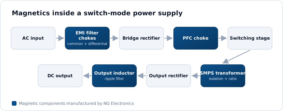


Winding quality is a matter of repeatability. NG Electronics is an ISO 9001:2015 certified manufacturer in Pune where ferrite transformers are wound, taped and varnished on one floor using semi-automatic winding machines. The winding order, layer count, tape build and lead dress agreed on the approved sample are what production follows for later batches, and batch records trace each lot to its raw material and production date.
Insulation is verified, not assumed. Insulation breakdown testers apply the hipot voltage between windings on every unit, impulse testers help reveal shorted turns and weak interlayer insulation, and LCR testers and automatic transformer testers confirm inductance and winding resistance. Materials are RoHS and REACH compliant, with certificate copies available on request. Design support is free against firm production intent, and overseas enquiries are welcome.
Call, WhatsApp or use the form with inductance, current and quantity.
Price, lead time and datasheet within 24 working hours.
Sample built in-house for your lab testing and approval.
Production with 100% electrical testing under ISO 9001:2015.
Packed with a test certificate, shipped across India or exported worldwide.
Answers about transformer winding configurations and insulation from NG Electronics, an ISO 9001:2015 certified company
The main configurations are simple layered, interleaved or sandwich, bifilar and sectional winding, using solid, multi-strand, litz or foil conductors. Insulation is built from wire enamel, interlayer tape, margin tape at the bobbin edges, sleeving on lead-outs and, where needed, triple-insulated wire. The right combination depends on voltage, frequency, current and the space available.
Interleaving places part of one winding on each side of another, for example primary, secondary, primary. This reduces the peak magnetic field between windings, which lowers leakage inductance and proximity-effect loss in the copper. The trade-offs are more insulation interfaces to build, extra terminations and higher capacitance between primary and secondary.
Clearance is the shortest distance through air between two conductors. Creepage is the shortest distance along the surface of insulating material between them. Both must meet the minimum set by the safety standard that applies to your end product, and those minimums depend on working voltage, pollution degree and insulation grade.
Triple-insulated wire is useful on small bobbins, where margins at both flanges would leave too little winding width. It lets the secondary occupy the full width, which improves coupling and can reduce core size. It costs more and is thicker than enamelled wire. Whether it is acceptable depends on the safety standard for your product.
Varnish mainly improves mechanical stability, moisture resistance and heat transfer, and it reduces audible noise by stopping turns and core halves from moving. On gapped cores the gap must stay undisturbed during impregnation, so inductance should be verified on the finished part.
Yes. If you have a drawing that defines winding order, wire, tape layers and margins, we build to it. If you only have electrical and insulation requirements, our engineers propose the construction. Custom samples are typically ready within 7 to 10 working days and are supplied free for lab approval.
How to specify a custom ferrite transformer: the design inputs a winder needs, from an ISO 9001:2015 certified
Learn more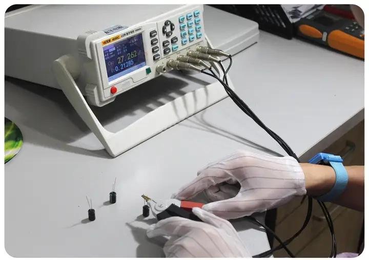
Transformer testing and design validation explained: inductance, leakage, turns ratio and hipot
Learn moreFlyback transformer manufacturer in Pune, ISO 9001:2015 certified
Learn more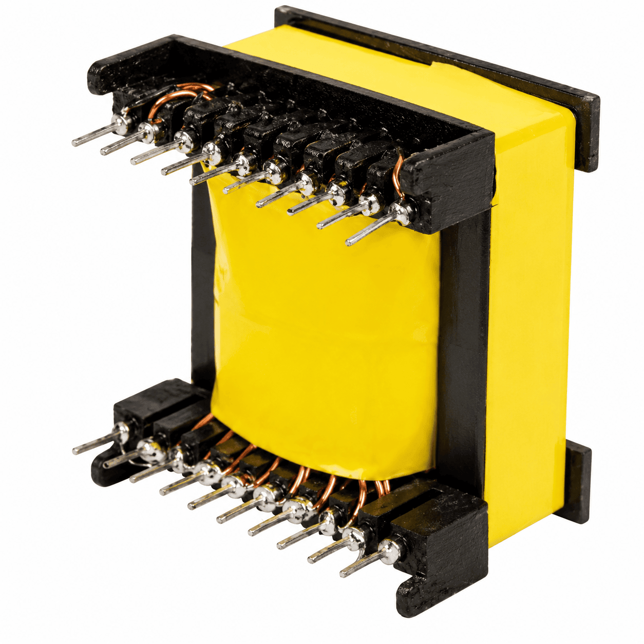
SMPS, flyback and custom high frequency transformers.
Learn moreSend your specification or drawing for transformer winding configurations and insulation. NG Electronics is an ISO 9001:2015 certified company, and every enquiry is answered by our engineering and sales team in Pune.



These products are limited, checkout within

Smart configuration workspace setup.


