


Common mode choke selection looks simple on a distributor search page: pick an inductance, pick a current, sort by price. In practice the part that results from that process often runs hot, saturates under real operating conditions or fails to deliver the attenuation the inductance figure implied. A choke is defined by more than two numbers, and a short, structured checklist prevents most of the mistakes that surface late in compliance testing.
The checklist below is organised in the order a design engineer or buyer would normally work: electrical ratings first, then impedance, core and winding construction, thermal and safety requirements, and finally what to ask the supplier. NG Electronics, an ISO 9001:2015 certified manufacturer in Pune, India, uses the same sequence when reviewing customer specifications for its common mode chokes, which span 250 mA to 50 A and 1 mH to 100 mH.
Key takeaways
- Rate the choke for RMS current at minimum input voltage and check peak current against saturation.
- Ask for impedance against frequency, not only inductance at a low test frequency.
- Core material and winding style set leakage inductance, isolation and high-frequency behaviour.
- Selection is complete only after a sample passes emission and temperature checks in the product.
Step 1: Confirm the electrical ratings
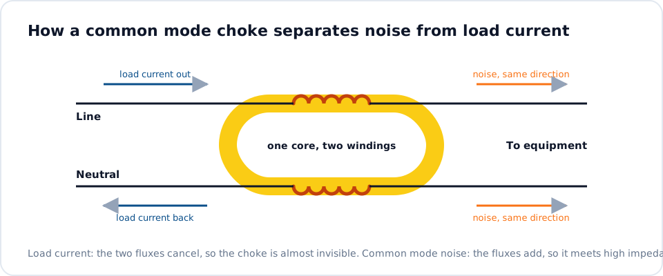
Start with the circuit, not the catalogue. Establish the maximum continuous RMS current through each winding at the lowest input voltage, since that is where input current peaks for a constant-power load. Add the peak current, including inrush. Balanced line current does not magnetise the core in the common mode sense, but it does drive the leakage flux of each winding, and at high peaks that flux can saturate a high-permeability core.
Then fix the voltage and the number of lines. A single-phase mains filter needs two windings, a three-phase filter three or four, and DC or signal lines may need two with close coupling. State the working voltage between windings and from windings to core, as these set the insulation and spacing. For currents beyond a few amperes, see the constructions on our high-current common mode choke page.
Step 2: Specify impedance across the noise band
Inductance on a datasheet is normally measured at a low frequency and a small signal level, typically 1 kHz or 10 kHz. It tells you where the filter corner frequency will fall, but not how the choke behaves at 1 MHz or 20 MHz. For that, ask for the impedance against frequency curve. Our guide on how to read an inductor datasheet explains the test conditions to look for.
Match the impedance peak to the frequencies where your emission scan shows the least margin. If the problem lies at the low end of the conducted band, you need inductance, which means permeability and turns. If it lies in the megahertz range, low winding capacitance matters more, and a choke with fewer turns may outperform one with a higher nominal inductance. Record the inductance tolerance too, as high-permeability cores typically carry wide tolerances.
Step 3: Choose core material and winding style
The two usual core materials are high-permeability MnZn ferrite and nanocrystalline alloy. Ferrite is economical and comes in toroidal and UU shapes; nanocrystalline gives more inductance per turn and holds its properties at higher temperature. The comparison of nanocrystalline and ferrite common mode chokes covers the trade-offs in detail. For most switch-mode supplies, a ferrite part of the kind shown on our common mode choke for SMPS page is the natural starting point.
Winding style has as much influence as the core. Sectional or split winding places each winding on its own part of the core, giving good insulation between lines and useful leakage inductance for differential mode filtering. Bifilar winding lays the wires side by side, minimising leakage and preserving signal integrity, at the cost of lower isolation between the lines. The article on leakage inductance in common mode chokes explains how to decide how much leakage you want.
Step 4: Check thermal, safety and mechanical fit
Copper loss is the square of the RMS current multiplied by the DC resistance of each winding, and it sets the temperature rise. Check the rise at maximum ambient temperature inside the enclosure, not on an open bench, and confirm that the total stays within the rating of the wire insulation and below the point where core permeability falls away. Where the choke bridges mains conductors, confirm the hipot test voltage and the creepage and clearance distances required by your safety standard.
Mechanical details cause as many delays as electrical ones. Confirm footprint and pin pitch against the PCB, the maximum height under the enclosure lid, whether the part is mounted vertically or horizontally, and how heavy parts are secured against vibration. For chassis-mounted high-current chokes, agree the lead length, lead termination and fixing method in advance. The summary below can be copied directly into a specification sheet or request for quotation.
- Current: continuous RMS, peak and inrush per winding
- Voltage: working voltage, hipot level and number of lines
- Inductance and tolerance, with test frequency and level
- Impedance at the critical noise frequencies
- Core material and winding style, including target leakage inductance
- Maximum DC resistance and permitted temperature rise at stated ambient
- Footprint, height, mounting and termination
Step 5: Complete common mode choke selection with a verified sample
The process is only finished when a sample has been measured in the product. Fit the sample, repeat the conducted emission scan at minimum and maximum line voltage, and measure the winding temperature at full load after it has stabilised. Compare the sample against the specification with an LCR meter so that you know what you approved, and keep that sample as the reference for incoming inspection of later deliveries.
Ask the supplier how production parts are tested and what records are kept. At NG Electronics every unit is electrically tested, covering inductance, DC resistance and hipot, with batch traceability to raw material and production date, and a test certificate is supplied on request. OEM buyers planning repeat volumes can review the OEM inductor manufacturing arrangements, and the contact page gives the quickest route to send a specification. Overseas enquiries are welcome.
Frequently asked questions
What inductance should I choose for a mains common mode choke?
Work back from the attenuation you need. Fix the Y capacitance allowed by the earth leakage limit, decide the corner frequency that gives the required attenuation at the lowest problem harmonic, and calculate inductance from the standard LC relation. Mains filters typically end up between a few millihenries and several tens of millihenries, depending on switching frequency and power level.
Why does my choke run hot when the inductance and current look right?
Heating is governed by DC resistance and RMS current, not by inductance. A part rated for a given current in free air may run much hotter inside a sealed enclosure next to other warm components. Check the actual RMS current at minimum input voltage, the DC resistance at operating temperature, and whether high-frequency ripple is adding core or proximity loss.
Can I order a small quantity for prototyping?
Yes. NG Electronics accepts orders of about 10 pieces for R&D and prototyping, and single-piece prototype samples are possible for custom designs. Stock items typically dispatch within 24 hours, and custom samples are typically ready within 7 to 10 working days. Production quantities for custom parts typically start from 100 to 1,000 pieces, depending on the design.
About NG Electronics
NG Electronics is a leading ISO 9001:2015 certified manufacturer of toroidal power inductors, common mode chokes, ferrite core transformers, line filter inductors, drum core inductors and custom wound magnetic components, based in Pune, India. Every part is wound and 100% electrically tested in-house. Copy the checklist into your specification and send it to NG Electronics at sales@ngelectronics.in for a technical quotation within 24 working hours and a sample for lab approval.




