


A light-emitting diode is a current-driven device: its brightness and colour depend on the current through it, not on the voltage applied. The driver therefore regulates current, and in a switching driver the inductor is the element that makes regulation efficient. Inductors for LED drivers decide how much ripple reaches the diodes, how large the driver is, how hot it runs inside a sealed luminaire and how much electrical noise it produces.
The sections below cover the common driver topologies, the calculation of inductance from ripple, the choice between shielded and unshielded parts and the filtering needed at the mains input. NG Electronics, an ISO 9001:2015 certified manufacturer in Pune, India, supplies drum core, toroidal and custom inductors along with flyback transformers for lighting, and welcomes enquiries from luminaire and driver makers in any country.
Key takeaways
- The inductor sets LED ripple current; typical targets are 20 to 40 per cent of the average current.
- Saturation current must exceed the average current plus half the ripple, with margin for temperature.
- Shielded drum cores reduce stray field at the cost of slightly earlier saturation.
- Check temperature rise in the finished housing, not on the open bench.
Driver topologies and the role of the inductor
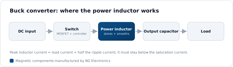
When the supply voltage is always higher than the LED string voltage, a buck converter is the natural choice, and the inductor sits in series with the string so that its current is the LED current. A boost converter is used when the string voltage exceeds the supply, as in battery-fed backlights, and a buck-boost or SEPIC stage handles supplies that range above and below the string. Mains-fed drivers that need isolation generally use a flyback transformer, which is a coupled inductor.
In each case the magnetic part stores energy during one part of the switching cycle and releases it during the other. The amount stored is E = 1/2 L I^2, so a driver delivering more current or running at a lower frequency needs a physically larger core. Raising the frequency shrinks the inductor but increases switching and core losses, and designers typically settle somewhere between tens of kilohertz and around 1 MHz depending on voltage and power.
Choosing inductors for LED drivers: inductance and ripple
For a buck driver the peak-to-peak ripple current equals the difference between input and output voltage, multiplied by the duty cycle and divided by the product of inductance and frequency. Rearranging gives the inductance for a chosen ripple. Because LEDs tolerate some ripple, designers typically allow 20 to 40 per cent of the average current, and sometimes more when an output capacitor is fitted across the string to smooth the current the diodes actually see.
Lower ripple improves light quality and reduces peak current, but it demands more inductance and therefore more turns, more resistance or a bigger core. Higher ripple shrinks the part but raises core loss and RMS current. The balance is explained in inductor ripple current explained. Whatever value is chosen, the saturation current rating must exceed the peak, which is the average plus half the ripple, with margin for tolerance and temperature.
Drum core, toroidal and shielded parts
Drum core inductors are widely used in LED drivers because they are compact, economical and easy to automate. NG Electronics produces drum core inductors from 1 µH to 1 mH in SMD, radial and axial styles. An unshielded drum has an open magnetic path, so part of its field spreads into the surrounding board. That is acceptable in many designs, but it can couple into current-sense traces or nearby filter components.
A shielded part adds a ferrite sleeve that closes most of the flux path, reducing stray field at the cost of slightly earlier saturation for the same size. Options are shown on the shielded drum core inductor page, and selection for low-voltage stages is covered under drum core inductors for DC-DC converters. Toroidal inductors suit higher currents, such as street lighting and high-bay drivers, where low DCR and a self-shielding shape are valuable.
Flyback transformers for isolated mains drivers
Isolated drivers for mains use most often employ a single-stage flyback, sometimes with power factor correction built into the same stage. The transformer stores energy in its air gap during the primary on-time and delivers it to the secondary afterwards, so primary inductance, turns ratio and peak current must be designed together. Leakage inductance should be low to limit the voltage spike on the switch, yet the insulation between windings must meet the safety requirement.
Those two aims pull in opposite directions, and the winding arrangement inside the bobbin is how they are reconciled. The fundamentals are set out in flyback transformer design basics. Ferrite core transformers on EE, EF, ETD and PQ cores are wound, taped and varnished in-house, with hipot testing on every unit, and the flyback transformer page lists the information needed for a quotation.
EMI, heat and lifetime
A driver connected to the mains must meet conducted emission limits, and lighting equipment is typically assessed against CISPR 15. A common mode choke with X and Y capacitors forms the input filter, and a small differential inductor is often added. Compact UU-core common mode chokes starting at 250 mA fit the narrow housings of linear and downlight drivers. Filter layout and component choice are discussed in EMI filters for LED drivers.
Heat is the other constraint. Drivers are frequently potted or enclosed with no airflow, and ambient temperature inside a luminaire can be high. Copper resistance rises with temperature, so the DCR measured at room temperature understates the loss in service. It is sensible to check temperature rise in the finished housing and to confirm that inductance at peak current still meets the design value when the part is hot.
- Topology, input voltage range and LED string voltage
- Average LED current and permitted ripple
- Switching frequency and maximum ambient temperature
- Package style: SMD, radial, axial or toroidal, shielded or unshielded
Frequently asked questions
How much ripple current is acceptable in an LED driver inductor?
Designers typically allow a peak-to-peak ripple of 20 to 40 per cent of the average LED current. A higher figure can be used if an output capacitor smooths the current through the diodes. The right value depends on the flicker and efficiency targets of the luminaire, and the saturation rating must always cover the resulting peak.
Should I use a shielded or unshielded inductor in an LED driver?
Unshielded drum cores cost less and saturate slightly later for a given size, so they suit drivers with space around the inductor. Shielded types are preferable on dense boards, near current-sense circuits or where radiated emissions are marginal, because the ferrite sleeve contains most of the stray magnetic field.
Can NG Electronics supply samples for a new driver design?
Yes. Stock items typically dispatch within 24 hours, and custom samples are typically ready within 7 to 10 working days after the specification is agreed. Around 10 pieces is a usual quantity for prototyping, and a free sample is provided for lab approval before production begins. Every production unit is electrically tested.
About NG Electronics
NG Electronics is a leading ISO 9001:2015 certified manufacturer of toroidal power inductors, common mode chokes, ferrite core transformers, line filter inductors, drum core inductors and custom wound magnetic components, based in Pune, India. Every part is wound and 100% electrically tested in-house. Send your LED driver specification to NG Electronics at sales@ngelectronics.in or call +91 83290 52861 for a technical quotation and samples for evaluation.




