

EMI in motor drives is a direct consequence of how a variable frequency drive works. The inverter builds an adjustable-frequency output by switching the DC link voltage onto the motor terminals thousands of times per second, and every switching edge is a fast voltage step. Those edges drive high-frequency currents through the motor cable, the motor frame and the earth system, and the same currents find their way back to the supply and into neighbouring control and communication wiring.
Because drives are installed in panels alongside PLCs, sensors and fieldbus networks, the consequences range from failed compliance tests to nuisance trips and corrupted signals on site. This article explains where the noise comes from, the paths it takes, and the filtering and installation measures that control it. NG Electronics, an ISO 9001:2015 certified manufacturer in Pune, India, supplies the common mode chokes and line filter inductors and reactors used in these filters.
Key takeaways
- A two-level inverter always produces a stepped common mode voltage, even when built perfectly.
- Common mode current flows through cable and motor capacitance and returns via earth.
- Input EMI filters, line reactors and output chokes or dv/dt filters each address a different part of the problem.
- Screened cable with full-circumference bonding is as important as the filter components.
Where EMI in motor drives comes from
A standard two-level, three-phase inverter connects each motor terminal to either the positive or the negative DC rail. With only those two choices per phase, the three output voltages can never sum to zero at any instant. Their average, the common mode voltage, therefore jumps in steps as the switches change state, at the switching frequency and with the edge speed of the power devices. This is inherent to the topology and is present even in a perfectly built drive.
Each step in common mode voltage is applied across the stray capacitances of the system: between cable cores and the cable screen or conduit, and between the motor windings and the stator frame. The current that flows follows the familiar relation i = C dv/dt, so faster edges and longer cables both increase it. Wide-bandgap devices switch faster than silicon IGBTs, which reduces switching loss but makes this noise source stronger.
The paths the noise takes
Common mode current leaves the inverter on all three motor conductors together and returns through earth: the cable screen, the motor frame, the building structure and the panel earth bar. If the return path back to the drive has high impedance, the current spreads through whatever else is bonded to earth, including signal cable screens and instrumentation. Part of it can also pass through the motor bearings, where repeated discharge is a recognised cause of premature bearing wear.
On the supply side, the same currents close their loop through the mains, where they are measured as conducted emissions. The rectifier front end adds low-frequency harmonics of the line frequency, which are a power quality matter and are handled separately from high-frequency EMI. Long motor cables introduce a further effect: voltage reflections at the motor terminals, which can approach twice the DC link voltage and stress the winding insulation.
Input-side filtering
The mains side of a drive is normally fitted with an EMI filter built from a three-phase common mode choke, X capacitors between phases and Y capacitors to earth. Its purpose is to give the high-frequency current a short return path inside the drive, so that it does not circulate through the supply network. Our introduction to three-phase EMI filter basics describes the arrangement. For drive currents of tens of amperes, a high-current common mode choke is the central component.
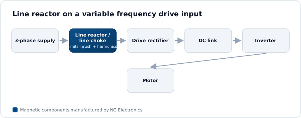
A line reactor or DC link choke is frequently added ahead of or after the rectifier. It is a differential mode component working at line-frequency harmonics, smoothing the pulsed rectifier current and limiting the effect of supply transients. It complements the EMI filter but does not replace it, because its inductance is fixed by harmonic and voltage-drop considerations, not by high-frequency attenuation. An AC line filter choke manufacturer can supply reactors and filter inductors as a matched set.
Output-side measures
Between drive and motor, the options increase in size and effect. A common mode choke threaded with all three motor conductors raises the impedance of the common mode loop and reduces the peak current, and with it bearing and earth currents. A dv/dt filter, typically a small inductor per phase with a damping network, slows the voltage edges and limits reflection overvoltage on long cables. A sine filter goes further and removes most of the switching content.
Output common mode chokes work under harder conditions than input chokes. The common mode current pulses are large, so the core must not saturate, and the core loss generated by absorbing the noise must be dissipated. Nanocrystalline cores are widely used here because they combine high permeability with high saturation flux density, as discussed in nanocrystalline versus ferrite common mode chokes. Cable length, switching frequency and DC link voltage should all be stated when specifying one.
Installation practice and component sourcing
Filters only work if the installation gives the noise a low-impedance path home. Use screened motor cable with the screen bonded around its full circumference at both the drive and the motor, keep the motor cable separate from signal and supply cables, and bond the filter and drive to the same unpainted metal backplate with short, wide connections. Long earth wires behave as inductors at these frequencies and defeat the filter.
Panel builders and drive manufacturers often need chokes sized to a particular drive frame and cable length. NG Electronics winds ring-core common mode chokes up to 50 A, including three-phase versions, along with line reactors for three-phase panels, and its EMI filter choke manufacturing page outlines the range. For a wider view of inductors and transformers on the factory floor, see magnetics in industrial automation.
Frequently asked questions
Why does a longer motor cable make drive EMI worse?
A longer cable has more capacitance between its conductors and its screen or the surrounding earthed metalwork. Each switching edge charges and discharges that capacitance, so the common mode current rises with length. Long cables also behave as transmission lines, producing voltage reflections at the motor terminals. Drive manufacturers therefore state maximum cable lengths with and without output filters.
Is a line reactor the same as an EMI filter?
No. A line reactor is a series inductor that works at harmonics of the supply frequency, reducing the peak rectifier current and improving the current waveform. An EMI filter targets the much higher frequencies generated by inverter switching, using a common mode choke with X and Y capacitors. Many installations need both, and they are designed to different criteria.
What information is needed to quote a choke for a drive?
NG Electronics would ask for the supply voltage and number of phases, rated and peak current, switching frequency, motor cable length, target inductance or impedance if known, ambient temperature and the mounting space available. With those details a technical quotation is normally returned within 24 working hours, followed by a sample for approval in your own test set-up.
About NG Electronics
NG Electronics is a leading ISO 9001:2015 certified manufacturer of toroidal power inductors, common mode chokes, ferrite core transformers, line filter inductors, drum core inductors and custom wound magnetic components, based in Pune, India. Every part is wound and 100% electrically tested in-house. Send your drive rating, cable length and filter requirement to NG Electronics at sales@ngelectronics.in for a technical quotation on common mode chokes and line reactors. Overseas enquiries are welcome.




