

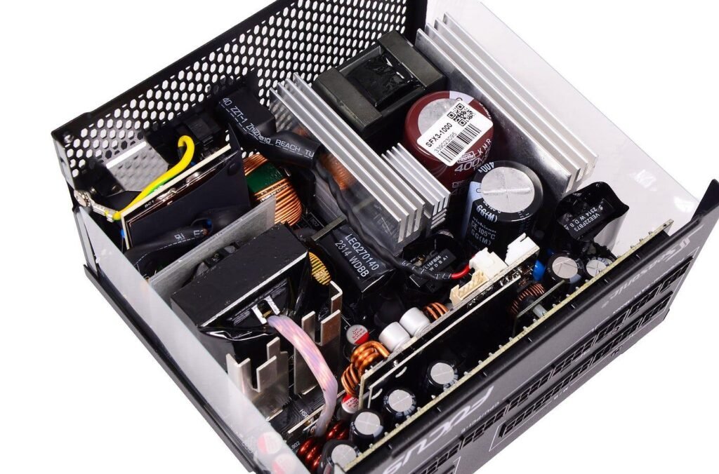
High frequency transformer losses decide how small a power converter can be made. Raising the switching frequency reduces the volt-seconds a transformer must support, which allows fewer turns or a smaller core, but every loss mechanism in the part becomes more severe as frequency rises. Beyond a certain point the transformer is limited by its temperature rise, not by saturation, and further size reduction is only possible if losses per unit volume are controlled.
This article describes where the losses arise and how designers reduce them. It is written by NG Electronics, an ISO 9001:2015 certified manufacturer in Pune, India, producing ferrite core transformers from under 1 VA to several hundred watts. The explanations use standard relations and typical values only; actual figures must always come from the data published by the ferrite and wire manufacturers for the chosen materials.
Key takeaways
- Core loss rises with frequency and steeply with flux swing; copper loss rises through skin and proximity effects.
- Total loss is typically lowest when core and copper losses are of similar size.
- Thin strands or foil, few layers, interleaving and distance from the gap keep AC resistance down.
- Leakage inductance and winding capacitance cause losses elsewhere in the converter that scale with frequency.
Where high frequency transformer losses come from
Losses divide into two groups. Core loss is generated in the ferrite by the alternating flux and depends on flux swing, frequency, material grade and temperature. Winding loss, often called copper loss, is generated by current in the conductors and depends on RMS current and on the effective resistance of the winding at the operating frequency, which can be several times its DC value. Smaller contributions come from dielectric loss in insulation and from energy lost in leakage inductance.
The two main groups trade against each other. Adding turns lowers the flux swing and therefore core loss, but lengthens the winding and raises copper loss. For a given core there is a number of turns at which total loss is lowest, and it typically lies where core and copper losses are of similar size. Since both end up as heat in the same small volume, the practical limit is the temperature rise the insulation system and the ferrite can accept.
Core loss in ferrite
Core loss in ferrite combines hysteresis loss, from repeatedly reversing the magnetisation, with eddy current and residual losses in the material. Manufacturers publish it as power per unit volume against flux density and frequency, and the curves are commonly approximated by the Steinmetz relation, in which loss is proportional to frequency raised to one exponent and peak flux density raised to another. For power ferrites the flux exponent is typically between two and three, so a modest reduction in flux swing lowers loss substantially.
Temperature matters too. Most power ferrite grades are formulated so that loss is lowest at an elevated temperature, typically somewhere between 60 and 100 °C, which discourages thermal runaway when the part is designed to operate near that point. Each grade also has a frequency band in which it performs best. A fuller treatment is given in inductor core losses explained, and the influence of geometry on cooling is discussed in ferrite core shapes compared.
Copper loss: skin effect, proximity effect and fringing
At high frequency, current crowds towards the surface of a conductor. The skin depth in copper is roughly 0.2 mm at 100 kHz and shrinks with the square root of frequency, so a thick round wire carries current only in its outer shell. In a multilayer winding the proximity effect is usually worse: the magnetic field from neighbouring layers induces circulating currents in each conductor, and the resulting loss grows rapidly with the number of layers.
Stranded litz wire is the usual answer for round-wire windings, and copper foil for high-current, low-turn windings, each with limits explained in our comparison of litz wire and solid wire in magnetics. Litz with too many strands wastes window area on insulation, so the strand diameter is matched to the frequency. Gapped parts such as flyback transformers and resonant inductors, including the custom wound inductors used alongside them, need particular care near the gap.
- Use strands or foil thinner than about twice the skin depth, typically.
- Keep the number of layers low by choosing a core with a wide winding window.
- Interleave primary and secondary sections to reduce the field across each layer.
- Keep turns clear of the air gap, where fringing flux induces eddy currents.
- Twist or transpose parallel conductors so that each shares current equally.
Leakage, capacitance and other parasitic losses
Leakage inductance stores energy that is not delivered to the load. In hard-switched converters that energy is dissipated in a snubber or clamp every cycle, so the associated loss rises in direct proportion to switching frequency. Winding capacitance is charged and discharged every cycle as well, adding switching loss in the semiconductors. Neither loss appears as heat inside the transformer, but both are caused by its construction and belong in its loss budget.
Faster devices sharpen these effects. Wide-bandgap switches permit higher frequencies and steeper edges, which shifts the emphasis towards low capacitance, controlled leakage and ferrite grades suited to higher frequency, as discussed in our article on the impact of GaN and SiC on magnetic components. In resonant and soft-switched topologies leakage energy is recycled instead of dissipated, which is one reason those circuits are favoured as frequency increases.
Reducing losses in practice
A practical approach is to set the allowed temperature rise first, estimate the total loss the chosen core can dissipate, and divide that loss between core and copper. The flux swing follows from the core-loss half, the turns follow from the flux swing, and the winding is then arranged to keep AC resistance low. If the copper loss cannot be met, a core with a larger window or a different shape is tried before the frequency is changed.
Measurement closes the loop. Temperature rise under real load, and input and output power measured with a power analyser, show whether the estimates hold. NG Electronics applies these considerations to the designs described on its high-frequency ferrite transformer and SMPS transformer pages and to higher power work such as ferrite transformers for EV chargers. Samples are provided for lab approval so that losses can be verified in the circuit where the part will be used.
Frequently asked questions
Which is larger at high frequency, core loss or copper loss?
It depends on the design, but a well-balanced transformer typically has core and copper losses of similar magnitude. If one dominates strongly, adjusting the turns usually reduces the total. At higher frequencies designers lower the flux swing to contain core loss, and use litz wire or foil to contain the rise in AC resistance.
Why does litz wire reduce transformer losses?
Litz wire divides the conductor into many thin, individually insulated strands that are twisted so each strand occupies every position in the bundle. With strands thinner than the skin depth, current distributes more evenly and skin and proximity losses fall. The benefit holds only within a frequency range; with unsuitable strand size, litz can perform worse than solid wire.
How are transformer losses measured?
The most direct check is temperature rise at full load in the real enclosure, measured with a thermocouple or by winding resistance change. Total converter loss can be found with a power analyser, and core loss can be estimated separately by exciting the transformer with no load. Calculated values should always be confirmed on a sample.
About NG Electronics
NG Electronics is a leading ISO 9001:2015 certified manufacturer of toroidal power inductors, common mode chokes, ferrite core transformers, line filter inductors, drum core inductors and custom wound magnetic components, based in Pune, India. Every part is wound and 100% electrically tested in-house. Share your power level, frequency and temperature limits with NG Electronics for a technical quotation and a sample you can verify thermally in your own converter.




