


Inductors have no semiconductor junctions, no electrolyte and no moving parts, so they are often treated as components that simply last. In practice they do fail, and when one does it frequently takes a switching device or a fuse with it. Understanding the common inductor failure modes helps a designer find the real cause instead of replacing the visible casualty and waiting for the fault to return.
Nearly all failures fall into four groups: thermal, magnetic, electrical and mechanical. Each leaves recognisable evidence and each has straightforward preventive measures at the design, manufacturing or sourcing stage. This article describes them in turn, and shows how the winding, testing and record-keeping practices used at NG Electronics address the manufacturing side of the problem for wound components of every size.
Key takeaways
- Sustained overheating is the most common root cause of inductor failure.
- Saturation usually damages the surrounding circuit before the inductor itself.
- Insulation breakdown develops from heat, voltage stress and mechanical damage together.
- Electrical testing of every unit catches winding and core defects before shipment.
Thermal inductor failure modes: overheating and ageing
Excess temperature is behind more failures than any other cause. It results from underestimated RMS current, high-frequency winding loss, core loss from heavy ripple, or an ambient hotter than assumed. The wire enamel darkens and becomes brittle, tapes lose adhesion, and eventually adjacent turns short together. A shorted turn acts as a loaded secondary: inductance collapses, local current rises sharply and the component then overheats quickly and visibly.
Some materials also change slowly with heat. Certain iron powder cores with organic binders can suffer thermal ageing when run hot for long periods, which increases core loss and so raises temperature further. Prevention is a matter of margin: calculate both copper and core loss at the hot resistance, confirm the rise by measurement in the enclosure, and choose an insulation class above the hot spot temperature. The method is set out in inductor temperature rise and derating.
Magnetic failures: saturation and its consequences
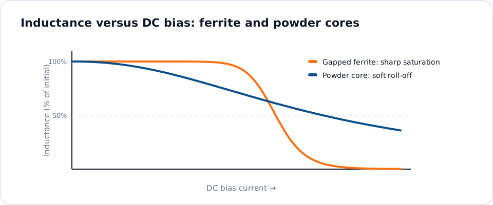
Saturation is reversible for the core, but not always for the circuit. When peak current exceeds the saturation rating, inductance drops and the current slope steepens within the same switching cycle. Unless current limiting acts quickly enough, the transistor sees a current spike well beyond its rating. The usual evidence is a failed switch with an inductor that still measures correctly on an LCR meter, which leads many investigations in the wrong direction.
Typical triggers are start-up into a discharged output capacitor, a load short circuit, input surges, and high ambient temperature, since ferrite saturation flux density typically falls as the core warms. Asymmetric drive in bridge converters can also walk a transformer core towards saturation. Prevention means checking peak current under every operating and fault condition, at maximum temperature and minimum inductance tolerance, and choosing a soft-saturating material where large transients are expected.
- Check saturation at the highest core temperature, not at room temperature.
- Include start-up, overload and short-circuit peaks in the current budget.
- Confirm the current limit responds faster than the inductor can saturate.
Electrical failures: insulation breakdown and open circuits
Insulation fails when voltage stress exceeds what the weakened material can withstand. Between turns the working voltage is normally small, but fast switching edges and mains surges can concentrate stress on the first few turns. Between windings, or from winding to core, the insulation must hold the full isolation voltage. Nicks in the enamel from sharp core edges or excessive winding tension create weak points that may pass initial testing and fail later.
Partial discharge in small air voids gradually erodes insulation in higher-voltage parts, which is one reason for the processes described in transformer varnish and impregnation. Open circuits are the other electrical failure: fine wire breaks at the termination through corrosion, overheated solder joints or repeated thermal cycling. Mains-connected parts sourced from an AC line filter choke manufacturer should carry a stated hipot voltage, and a high current common mode choke needs terminations sized for its full load current.
Mechanical failures: cracks, vibration and handling
Ferrite is a brittle ceramic. A dropped part, an over-tightened clamp or board flexing during assembly can crack the core, and a crack behaves as an unintended air gap. The inductance falls, sometimes only slightly, yet enough to raise ripple and peak current. Mismatched thermal expansion between a rigid potting compound and the core can also produce cracks after repeated temperature cycles, and with some ferrites mechanical stress alone lowers permeability.
Vibration is the main hazard for heavy components. A large toroid held only by its leads will eventually fatigue the solder joints or the wire where it leaves the winding. Adhesive, a mounting base, cable ties or a clamp should carry the mass, leaving the leads to carry current only. Audible noise from magnetostriction or loose turns is not a failure in itself, although it can indicate a winding that is free to move and abrade its insulation.
Prevention through design, testing and sourcing
A complete specification is the first defence. State peak and RMS current, ripple and frequency, maximum ambient, isolation voltage, mounting method and any vibration or humidity requirements, so that the part is designed for the real conditions. Then test samples in the product at worst-case input, load and temperature. When a failure does occur, examine the returned part for discolouration, measure inductance, DCR and insulation resistance, and compare them with a known good unit.
Manufacturing controls close the remaining gaps. NG Electronics, an ISO 9001:2015 certified manufacturer in Pune, India, electrically tests 100 percent of units for inductance, DCR, Q factor, saturation current and hipot, and keeps batch records for traceability, as described under quality assurance. Impulse testers help reveal shorted turns that a simple inductance check may miss. For supplier evaluation see how to choose a magnetics manufacturer; for a redesign, our custom wound inductors page and our profile as a magnetic components manufacturer in India explain the options, or simply contact our engineering team.
Frequently asked questions
What is the most common cause of inductor failure?
Overheating is the most frequent root cause. Excess copper or core loss, or a higher ambient than the design assumed, degrades the wire insulation until turns short together. Once a shorted turn forms, inductance drops and heating accelerates. Verifying temperature rise in the actual enclosure at worst-case load is the most effective single preventive step.
How can I tell whether an inductor has failed?
Look for discoloured or cracked insulation and a burnt smell, then measure inductance and DCR and compare them with the specification or a good sample. A marked drop in inductance or Q suggests shorted turns or a cracked core, while an open reading indicates a broken winding or termination. Check insulation resistance to the core as well.
Can a saturated inductor be reused?
Saturation alone does not damage a core; once the current falls, the inductance returns. The danger lies in the overcurrent it causes, which may have overheated the winding or destroyed the switch. If the inductor shows no thermal damage and measures within tolerance it can typically be reused, but the cause of the saturation must be corrected.
About NG Electronics
NG Electronics is a leading ISO 9001:2015 certified manufacturer of toroidal power inductors, common mode chokes, ferrite core transformers, line filter inductors, drum core inductors and custom wound magnetic components, based in Pune, India. Every part is wound and 100% electrically tested in-house. If an inductor in your product is running hot or failing in the field, send the operating conditions to NG Electronics for a review and a technical quotation within 24 working hours.




