


Stationary batteries are now installed beside solar plants, in commercial buildings and at grid substations, and every one of them connects through a power conversion system. Inductors for battery energy storage systems are found throughout that conversion chain. They control the ripple current flowing into the cells, shape the current exchanged with the grid and suppress the noise generated by fast switching. Because power flows in both directions, they have to perform equally well when charging and discharging.
This guide looks at the inductive components in a typical storage converter, the electrical demands on each and the practical points to settle before ordering. NG Electronics, an ISO 9001:2015 certified manufacturer in Pune, India, builds toroidal and custom wound inductors and common mode chokes with full in-house testing, and is glad to receive enquiries from storage integrators and converter designers abroad.
Key takeaways
- The DC-DC inductor works in both directions and sees its highest current at minimum battery voltage.
- Battery ripple current limits should drive the choice of inductance.
- Interleaved phases reduce ripple at the battery and share current between inductors.
- Give the full operating envelope when requesting a design, not a single nominal point.
Where inductors for battery energy storage systems are used
A storage converter usually has two stages. A bidirectional DC-DC converter sits between the battery and a DC link, working as a buck stage when charging and a boost stage when discharging. A bidirectional inverter then connects the DC link to the AC network through a filter. Some systems omit the DC-DC stage and connect a high-voltage battery directly to the inverter, and others couple the battery to the DC side of a solar inverter.
Each arrangement needs power inductors in the DC-DC stage, filter inductors on the AC side and common mode chokes on both. Smaller parts appear in the battery management and auxiliary supplies. The ratings differ widely between a residential unit of a few kilowatts and a containerised system, but the design reasoning set out below scales with power, and the same questions about inductance, saturation, loss and cooling apply at every size.
Bidirectional DC-DC inductors
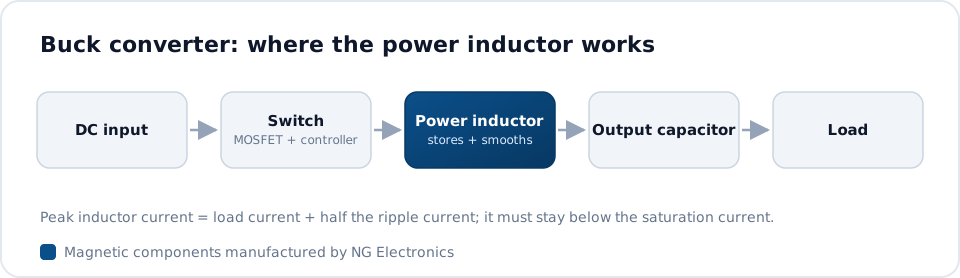
In the DC-DC stage the same inductor serves both directions of power flow, so its average current can be positive or negative while the ripple remains triangular. The ripple amplitude follows V = L di/dt: the voltage across the winding during the on-time, multiplied by that time and divided by inductance. The highest average current typically occurs when the battery is near its minimum voltage and the system is delivering full power.
Stored energy is E = 1/2 L I^2, so the core volume needed grows with the square of peak current. Powder cores with a distributed gap are the typical choice, since their gradual saturation gives the control loop time to react during faults. For larger ratings, NG Electronics winds high-current toroidal inductors with heavier gauge or multi-strand copper, and related charger designs are described on the battery charger inductor page.
Ripple current, interleaving and battery life
Cell manufacturers typically specify a limit on the alternating current superimposed on the charge or discharge current, because ripple causes additional heating in the cells. The inductor, together with the battery-side capacitor, sets that ripple. A larger inductance reduces it but adds copper, weight and cost, so the target should come from the battery data rather than from habit, and it should be agreed before the magnetic design begins.
Interleaving offers another route. Two or more phases, each with its own inductor, are switched with a phase shift so that their ripple currents partly cancel at the battery terminals. Each inductor carries only a share of the total current, which eases saturation and thermal design and spreads the heat. Matching between phases then becomes important, so inductance tolerance and DCR tolerance should be stated on the drawing.
Grid-side filters and common mode chokes
The inverter connects to the network through an L or LCL filter, whose inductors carry mains-frequency current with switching ripple superimposed. Their design follows the approach used in solar and UPS equipment, covered in magnetics for UPS and energy storage. Standard toroidal power inductors span 10 µH to 10 mH at up to 25 A, with custom parts available beyond that range for higher inductance or current.
A battery rack has considerable capacitance to its earthed enclosure, so common mode voltage from the converter can drive current through the rack structure and cabling. Common mode chokes on the DC and AC sides limit this current and help the system meet conducted emission requirements. Constructions for larger currents, including three-phase types up to 50 A, are shown on the high-current common mode choke page.
Thermal design and specification
Storage systems may cycle daily at high power for many years, often inside containers or cabinets with controlled but limited cooling. Copper loss and core loss should be calculated at the worst operating point and the resulting temperature rise confirmed by test; the method is described in inductor temperature rise and derating. Insulation class and creepage must suit the system voltage, which in larger installations can be high.
When requesting a quotation, it helps to give the full operating envelope rather than a single nominal point. Custom wound inductors are designed against that envelope on ferrite, iron powder, MPP, Sendust, High Flux or nanocrystalline cores, and the custom toroidal inductor page explains the sample and approval steps. The items below cover what a designer usually needs to begin.
- Battery voltage range and DC link voltage
- Maximum charge and discharge current, and permitted ripple
- Switching frequency and number of interleaved phases
- Inductance at zero and peak current, with tolerance
- Ambient temperature, cooling method and insulation test voltage
Frequently asked questions
What does the inductor do in a bidirectional battery converter?
It stores and releases energy every switching cycle, allowing the converter to step voltage down when charging and up when discharging. It also limits the rate of change of current, which sets the ripple seen by the battery. One inductor serves both directions, so it must be rated for the worst-case current in either mode.
Why is ripple current a concern for batteries?
Alternating current superimposed on the charge or discharge current produces extra heating in the internal resistance of the cells without transferring useful energy. Cell manufacturers typically publish a ripple limit for this reason. Adequate inductance, a battery-side capacitor and interleaved phases are the usual ways to keep the ripple within that limit.
Can NG Electronics design an inductor for a storage converter?
Yes. Design support is free against firm production intent. Share the operating envelope and mechanical limits, and a technical quotation is typically returned within 24 working hours. A free sample follows for lab approval, and production units are 100 per cent electrically tested for inductance, DCR, saturation current and hipot.
About NG Electronics
NG Electronics is a leading ISO 9001:2015 certified manufacturer of toroidal power inductors, common mode chokes, ferrite core transformers, line filter inductors, drum core inductors and custom wound magnetic components, based in Pune, India. Every part is wound and 100% electrically tested in-house. Send your storage converter inductor specification to NG Electronics at sales@ngelectronics.in for a technical quotation, typically within 24 working hours, and a sample for lab approval.




