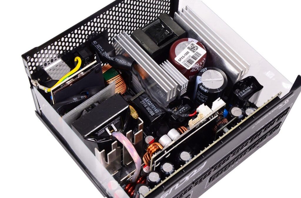
Power electronics component trends are easier to follow when you ignore the headlines and look at what converter designers are actually being asked to deliver: more power in less volume, higher efficiency across the load range, cleaner emissions and a supply chain that does not stall a product launch. Each of these pressures lands on the passive components, and particularly on inductors, chokes and transformers, which remain the largest and often the warmest parts on a power board.
This article describes the main engineering directions qualitatively and without forecasts. It is written for design engineers who need to anticipate what their next specification will look like, and for purchase managers who want to understand why the magnetics on a new project may not resemble those on the last one. Where it helps, the text points to more detailed guides on individual topics.
Key takeaways
- Higher switching frequency shifts magnetics from saturation-limited to loss-limited design.
- Electrification brings higher voltages, sustained load and bidirectional power flow.
- Power density makes loss budgets and mechanical detail part of the specification.
- Buyers increasingly weigh traceability, customisation and second sources alongside price.
Power electronics component trends at a glance
Five directions account for most of the change. Switching devices based on gallium nitride and silicon carbide are moving converters to higher frequencies. Electrification of transport and energy is raising voltages, currents and the number of bidirectional stages. Power density targets are compressing the space available for magnetics and heat removal. Electromagnetic compatibility is being addressed earlier in the design cycle. Finally, buyers are placing more weight on traceability, customisation and second sources than on unit price alone.
None of these directions is new in principle, and they interact. A higher switching frequency reduces the inductance needed for a given ripple but increases core loss and broadens the noise spectrum. A higher bus voltage reduces current for the same power but demands more insulation. The practical consequence is that magnetic components are specified with more parameters than before, and fewer designs can be completed with a part chosen on inductance and current rating only.
Wide-bandgap switching and higher frequencies
The standard ripple relation for a buck stage, ripple = V x D / (L x f), shows why frequency matters: doubling f halves the inductance needed for the same ripple current. Wide-bandgap transistors make that step affordable in terms of switching loss. The magnetics then become loss-limited instead of saturation-limited, so the choice of core material grade and conductor type moves to the middle of the design. The companion article on how GaN and SiC affect magnetic components treats this in detail.
Soft-switching and resonant topologies are also more widely used, because they avoid much of the loss that hard switching would otherwise incur. In these circuits the transformer's leakage and magnetising inductances are functional circuit elements with tolerances, not parasitics to be reduced as far as possible. That favours purpose-built ferrite core transformers whose winding arrangement, gap and core shape are fixed by the resonant tank, and it makes consistency between samples a formal requirement, verified by measurement on each batch.
Electrification: solar, storage and vehicle charging
Solar inverters, battery storage converters and EV chargers share several traits: high DC bus voltages, continuous operation at significant power, outdoor or semi-outdoor temperatures and long expected service lives. Their inductors carry a large low-frequency or DC component with switching ripple superimposed, so saturation behaviour under bias and temperature rise under sustained load are the governing parameters. A toroidal inductor for a solar inverter is a typical example, chosen for its closed magnetic path and efficient use of copper.
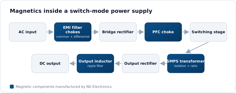
Bidirectional operation is increasingly requested, so that the same hardware can charge and discharge a battery. Magnetics in such stages must be characterised for power flow in both directions, and the isolation transformer sees symmetrical stress. Guides to magnetics for EV chargers and inductors for battery energy storage systems explain how the boost choke, isolation transformer and output filter divide the work in these systems, and which parameters each one should be specified against.
Power density, thermal limits and integration
As enclosures shrink, the loss in each component matters more than its nominal rating. A compact inductor with less surface area must dissipate less heat for the same temperature rise, so designers typically work from a loss budget and a hot-spot temperature limit. Low-profile core shapes, flat or multi-strand conductors and thermally conductive potting are common responses. Integration is another: combining two functions on one core, or using a transformer's leakage inductance in place of a separate resonant inductor.
Integration saves volume but makes the component specific to one design, which increases the value of a manufacturer who can iterate quickly. It also raises the importance of mechanical detail: lead position, mounting, clearance to neighbouring parts and airflow direction. Where an isolated supply is involved, an SMPS transformer manufacturer should be given the full mechanical envelope and cooling conditions along with the electrical data, since the two cannot be settled separately at high power density.
EMC, compliance and what buyers now ask for
Faster edges push conducted and radiated noise higher in frequency, and emission standards such as CISPR 32 and CISPR 14 still have to be met. Filter design is therefore being started alongside the power stage instead of after the first failed test. Common mode chokes on high-permeability MnZn ferrite or nanocrystalline cores are selected for impedance across a band, and winding styles such as sectional or split winding are used to control parasitic capacitance and leakage inductance.
On the purchasing side, the trend is towards documented quality and flexible supply. NG Electronics is an ISO 9001:2015 certified manufacturer in Pune, India, and works as an OEM inductor manufacturer for customers who need parts built to their own drawings. Every unit is electrically tested, batch records give traceability to raw material and production date, and RoHS and REACH compliant materials are used, with certificate copies available on request. Overseas enquiries are welcome.
Frequently asked questions
Which trend affects inductor design the most?
Higher switching frequency has the broadest effect. It lowers the inductance needed for a given ripple, which permits smaller cores, but it raises core loss and AC winding resistance and widens the noise spectrum. The design moves from being limited by saturation to being limited by temperature rise, so material grade, conductor type and cooling all need closer attention.
Are standard catalogue magnetics still suitable for new designs?
Often, yes. Standard toroidal, drum core and common mode parts cover many filter and converter positions, and stock items are quick to obtain. Custom parts become worthwhile when the frequency, mechanical envelope, insulation requirement or resonant behaviour falls outside catalogue characterisation. Many products use a mixture of both, reserving custom magnetics for the positions that define performance.
How does NG Electronics support new power designs?
NG Electronics provides a technical quotation, typically within 24 working hours of receiving a specification, followed by a free sample for laboratory approval. Custom samples are typically ready within 7 to 10 working days. Design support is free against firm production intent, and production units are fully electrically tested, with a test certificate supplied on request.
About NG Electronics
NG Electronics is a leading ISO 9001:2015 certified manufacturer of toroidal power inductors, common mode chokes, ferrite core transformers, line filter inductors, drum core inductors and custom wound magnetic components, based in Pune, India. Every part is wound and 100% electrically tested in-house. Share the specification for your next converter with NG Electronics to receive a technical quotation and a sample for laboratory approval.