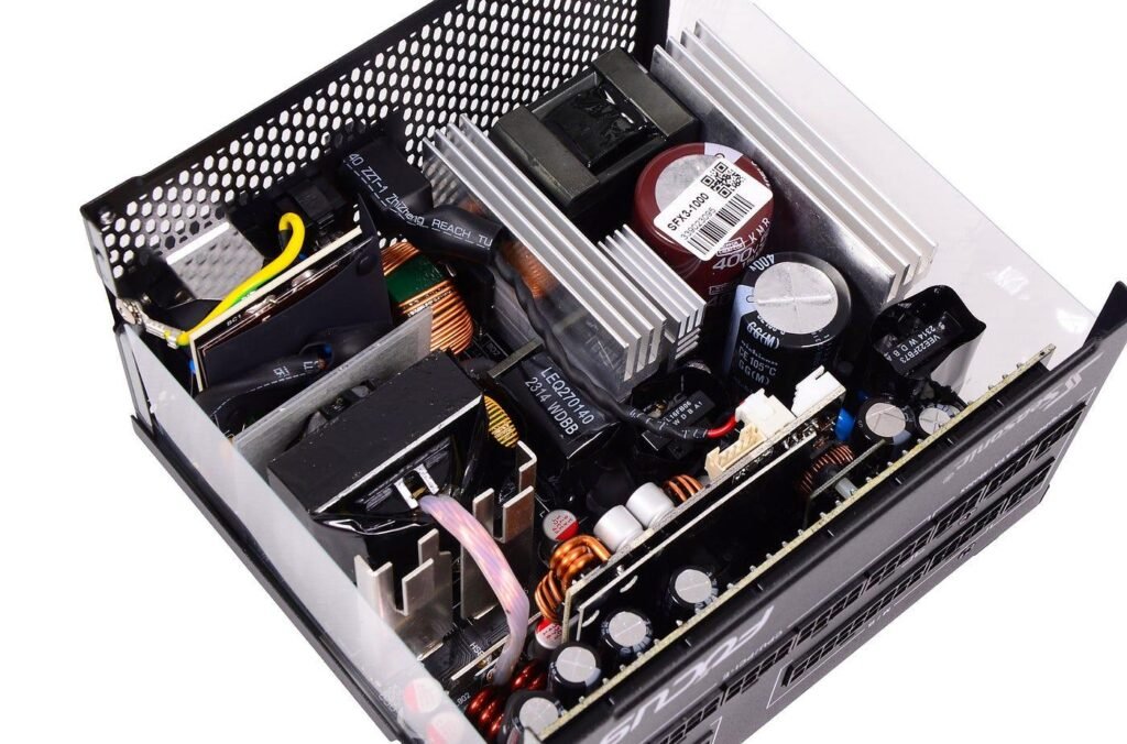
Radiated vs conducted EMI is the first distinction every electromagnetic compatibility test plan draws, and it shapes how a product is measured, where it tends to fail and which fixes will help. The two terms describe the route by which unwanted high-frequency energy leaves a product: along its cables, or through the air. They are measured with different equipment over different frequency ranges, yet they originate from the same switching events inside the circuit.
Treating them as unrelated problems leads to wasted effort, such as adding shielding to cure noise that is actually leaving along the mains lead. This article explains the difference, why the frequency boundary sits where it does, how one type converts into the other, and which components address each. NG Electronics, an ISO 9001:2015 certified manufacturer in Pune, India, makes the common mode chokes and filter inductors used against both.
Key takeaways
- Conducted EMI leaves along cables and is typically measured from 150 kHz to 30 MHz with a LISN.
- Radiated EMI leaves as a field and is typically measured from 30 MHz upward with an antenna.
- Common mode current on cables links the two: it appears in conducted scans and drives cable radiation.
- Identify the failing test, frequency and path before choosing a filter, layout or shielding fix.
Conducted EMI: noise that travels along cables
Conducted emissions are noise voltages and currents carried on the conductors connected to the product, chiefly the power input. They are measured with a line impedance stabilisation network, which gives the product a repeatable source impedance and couples the noise to a measuring receiver. For mains-powered equipment the measured band typically runs from 150 kHz to 30 MHz, with some product standards starting lower. The test can be reproduced on an ordinary laboratory bench.
The noise has two components. Differential mode noise circulates between the supply conductors and is driven mainly by the pulsed input current of the converter. Common mode noise flows on all conductors together and returns through earth, driven by fast voltage edges acting on stray capacitance. Both are reduced with an input filter, and the method is set out in our step-by-step EMI filter design guide, which starts from a measured spectrum.
Radiated EMI: noise that travels through space
Radiated emissions are electromagnetic fields launched from the product and its cables. They are measured with an antenna at a set distance on an open test site or in an anechoic or semi-anechoic chamber, typically from 30 MHz upward, with the upper limit depending on the highest frequencies used inside the product. The test needs a controlled environment, which makes it more expensive to repeat than a conducted scan.
Two structures do most of the radiating. Current loops on the circuit board act as small loop antennas, and their emission rises with loop area, current and the square of frequency. Cables act as wire antennas when common mode current flows along them, and because a cable is far longer than any board loop, a few microamperes of common mode current on a lead can exceed the emission of the whole board.
Radiated vs conducted EMI: why the boundary sits near 30 MHz
The split is a matter of wavelength. At 150 kHz the wavelength is two kilometres, and at 30 MHz it is ten metres. A structure radiates efficiently only when its length is a reasonable fraction of the wavelength, so at the lower frequencies a typical product and its cables are poor antennas, and the noise mostly stays on the wiring, where it can disturb other equipment on the same supply.
Above about 30 MHz, cables of a metre or two become effective antennas, and the noise is more likely to leave as a field. The boundary is a convention, not a physical wall. Conducted noise near the top of its band is often the same common mode current that causes radiated failures just above it, which is why a filter that performs poorly at high frequency can hurt both results.
How the same source produces both
Inside a switch-mode converter, the sources are the switching node, with its fast voltage edges, and the loops carrying fast-changing current. The switching fundamental and its lower harmonics dominate the conducted band. The edges themselves, and the ringing that parasitic inductance and capacitance superimpose on them, contain energy at tens to hundreds of megahertz and dominate the radiated band. One switching event therefore feeds both measurements.
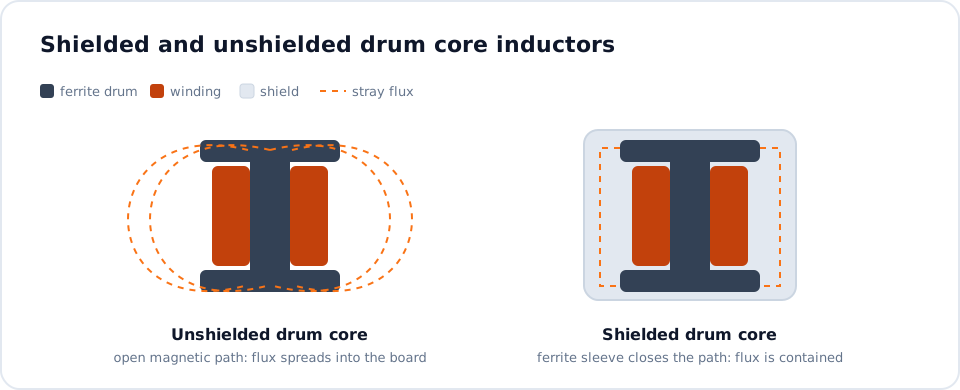
Magnetic components play a part in both. An unshielded inductor has a stray field that couples into nearby tracks and into the input filter, bypassing it. Shielded constructions confine the field, which is one reason designers choose parts from a shielded drum core inductor supplier for compact DC-DC stages. Above its self-resonant frequency an inductor behaves as a capacitor, a point covered in our article on Q factor and self-resonant frequency.
Choosing the right fix for each type
Start by identifying which test is failing and at what frequency, then work on the path involved. Reducing the noise at source helps both types; beyond that, the measures differ, as the list below shows. NG Electronics supplies drum core inductors in shielded and unshielded forms and builds filter chokes to customer requirements through its EMI filter choke manufacturing service, with samples available for laboratory trials.
A sound sequence is to pass conducted emissions first, because the equipment is simple and the filter work also lowers the common mode current that drives cable radiation. Our guide on how to pass conducted emissions testing covers that stage. Then check radiated emissions with the final cables and enclosure fitted. For power supply inputs, a common mode choke for SMPS use with low winding capacitance keeps its impedance further into the megahertz range.
- Conducted, differential mode: X capacitors and series line inductance.
- Conducted, common mode: common mode choke with Y capacitors to earth.
- Radiated from the board: smaller current loops, solid return planes, shielded inductors, snubbers and controlled edge rates.
- Radiated from cables: common mode chokes or ferrites on the leads, good screen termination and filtering at the connector.
Frequently asked questions
Can a product pass conducted emissions and still fail radiated emissions?
Yes, and it is common. The conducted test stops at 30 MHz for most products, so noise above that frequency is not assessed by it. Fast switching edges, ringing and common mode current on cables can all produce radiated failures in a product whose input filter performs well in the conducted band. Each test must be passed in its own right.
Does a common mode choke help with radiated EMI?
It can. Radiation from cables is driven by common mode current, and a choke raises the impedance of that path, reducing the current. The choke must still present useful impedance at the failing frequency, which calls for low winding capacitance and a suitable core material. A choke chosen only for the conducted band may have little effect at 100 MHz.
Which should I test first during development?
Conducted emissions are usually tested first, because a LISN and a spectrum analyser on a bench give repeatable results at modest cost. Radiated pre-compliance checks with near-field probes can run alongside. NG Electronics can provide sample chokes in alternative inductance values so that filter options can be compared on the bench before a formal laboratory booking.
About NG Electronics
NG Electronics is a leading ISO 9001:2015 certified manufacturer of toroidal power inductors, common mode chokes, ferrite core transformers, line filter inductors, drum core inductors and custom wound magnetic components, based in Pune, India. Every part is wound and 100% electrically tested in-house. Tell NG Electronics which emission test is failing and at what frequency, and request a choke or inductor proposal at sales@ngelectronics.in. A technical quotation is returned within 24 working hours.