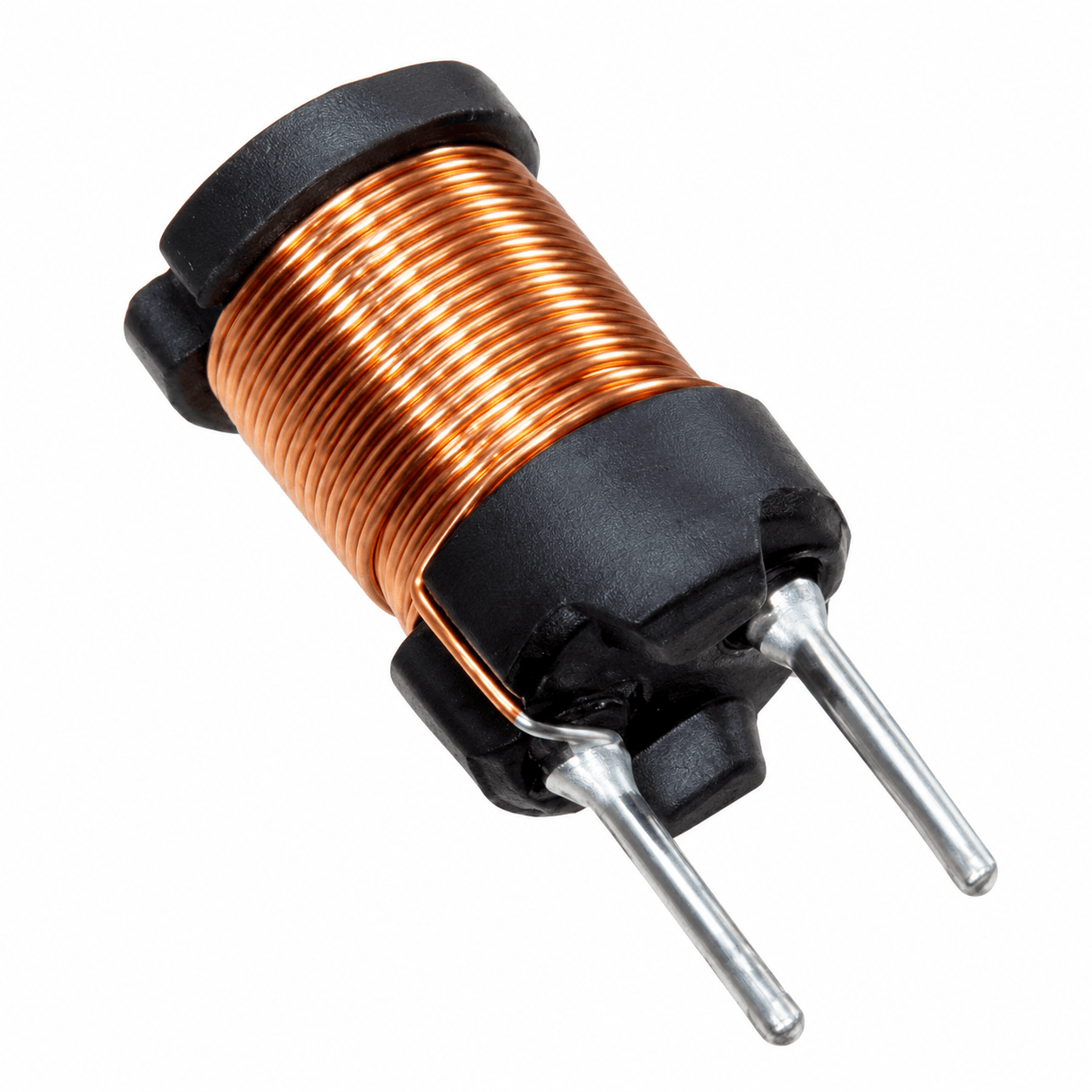

An inductor that passes every electrical test at room temperature can still fail early if it runs too hot inside the finished product. Inductor temperature rise is the difference between the hottest part of the component and the surrounding air, and it determines the life of the wire enamel, tapes and varnish that hold the winding together. In continuously loaded equipment it is frequently the true limit on current, ahead of saturation.
This guide explains where the heat originates, how a thermal current rating is defined on a datasheet, and how to derate that rating for a hot enclosure or restricted airflow. It also describes a simple way to measure winding temperature on the bench. The approach mirrors how NG Electronics reviews thermal margins when a customer shares operating conditions for a new wound component.
Key takeaways
- Total heating is copper loss plus core loss; both must be included.
- Thermal current ratings usually assume a 40 °C rise in still air on a test board.
- Hot spot temperature equals ambient plus rise and must suit the insulation class.
- Because copper loss follows current squared, modest current reduction gives real relief.
Where the heat in an inductor comes from
Two sources contribute. Copper loss is the square of the RMS current multiplied by the winding resistance. At switching frequencies the ripple component sees a higher effective resistance than the DCR because of skin and proximity effects, so the alternating and direct parts should be calculated separately when ripple is large. Core loss is the second source and depends on the alternating flux swing and frequency, not on the load current.
Copper resistance itself increases with temperature, by roughly 0.4 percent per kelvin. A winding that has warmed by 60 K dissipates about a quarter more than the room temperature calculation suggests, which warms it further until equilibrium is reached. Any loss estimate should therefore use the hot resistance. Reading these figures correctly from a specification is covered in how to read an inductor datasheet, including the conditions under which DCR is quoted.
How inductor temperature rise ratings are defined
A thermal current rating states the direct current that produces a given rise, most often 40 °C, with the part mounted on a specified board in still air. The rise depends on total loss and on how well the surface sheds heat by convection and radiation, so larger parts with more exposed surface run cooler for the same dissipation. The rating normally includes copper loss only; core loss from your actual ripple adds to it.
The test board matters as well. Wide copper traces carry heat away from the terminals, and a rating obtained on generous copper will not be reproduced on thin tracks or beside a hot semiconductor. Open constructions such as single-layer toroidal power inductors expose most of the winding to air, whereas potted, sleeved or multilayer parts trap more heat inside. Treat the published number as a comparison between components, then verify in the real enclosure.
Insulation classes and the hot spot limit
Insulating materials are grouped by thermal class, a standardised maximum temperature at which they give an acceptable service life. Common classes are B at 130 °C, F at 155 °C and H at 180 °C. The limit applies to the hottest point inside the winding, which is warmer than the surface. A widely used rule of thumb holds that insulation life roughly halves for every 10 K increase in operating temperature, so margin is valuable.
The core imposes its own ceiling. Ferrite saturation flux density typically declines as temperature climbs, so a hot core saturates at a lower current than a cold one. Some iron powder materials with organic binders can age when held at elevated temperature for long periods, gradually increasing core loss. Finishing processes help with heat transfer and mechanical stability, as explained in transformer varnish and impregnation, but they do not raise the class of the underlying materials.
- Hot spot temperature = maximum ambient + temperature rise.
- Keep the hot spot below the lowest-rated material in the assembly.
- Check saturation current at the hot core temperature, not at 25 °C.
Derating current for ambient and airflow
Start with the allowed rise: the maximum component temperature minus the highest local ambient. Suppose a part is rated 10 A for a 40 K rise and has a 125 °C limit. At 85 °C ambient the full 40 K is available. At 105 °C only 20 K remains. Since copper loss follows the square of current and rise is approximately proportional to loss, the usable current is about 10 A multiplied by the square root of 20 over 40, close to 7 A.
That estimate ignores core loss, which does not fall when load current is reduced, so the true figure will be somewhat lower in a high-ripple design. Altitude, sealed enclosures and neighbouring heat sources reduce it further, while forced air improves it considerably. For heavy continuous loads it is often more economical to choose a larger core or heavier copper from a high current toroidal inductor manufacturer than to add cooling, particularly for a toroidal inductor in a solar inverter expected to run for many years outdoors.
Measuring and verifying temperature rise
The resistance method gives the average winding temperature without embedded sensors. Measure the winding resistance cold at a known temperature, run the unit at full load until readings stabilise, then switch off and measure resistance again quickly. For copper, the hot temperature equals the hot-to-cold resistance ratio multiplied by 234.5 plus the cold temperature, minus 234.5. Thermocouples fixed to the winding surface or a thermal camera then locate hot spots.
Sustained overheating is a leading cause of the problems described in inductor failure modes and prevention, so the test is worth doing on early samples. NG Electronics is an ISO 9001:2015 certified manufacturer in Pune, India, and supplies free samples for laboratory approval so that rise can be checked in the customer's enclosure. Mains-side parts such as line filter inductors are verified in the same way, and an OEM inductor manufacturer can adjust wire gauge or core size if margin is short. Our quality assurance page lists the electrical tests applied to every unit.
Frequently asked questions
What is a typical inductor temperature rise rating?
Many power inductor datasheets define the thermal current as the direct current causing a 40 °C rise above ambient in still air, though some use 20 °C or another figure. The rating usually covers copper loss only and assumes a particular test board. Always read the stated rise and conditions before comparing the current ratings of two parts.
How do I derate an inductor for high ambient temperature?
Subtract the maximum ambient from the maximum component temperature to find the allowed rise. If that is less than the rated rise, reduce the current by approximately the square root of the ratio of allowed rise to rated rise. Then make a further allowance for core loss and poor airflow, and confirm by measurement in the real product.
Can NG Electronics design for a specific temperature limit?
Yes. If the specification states maximum ambient, permitted rise or hot spot limit, and cooling conditions, NG Electronics will select wire gauge, core size and insulation materials to suit. A sample is supplied for laboratory approval so the rise can be measured in the application before production, and design support is free against firm production intent.
About NG Electronics
NG Electronics is a leading ISO 9001:2015 certified manufacturer of toroidal power inductors, common mode chokes, ferrite core transformers, line filter inductors, drum core inductors and custom wound magnetic components, based in Pune, India. Every part is wound and 100% electrically tested in-house. Send NG Electronics your current, ambient temperature and permitted rise, and receive a technical quotation within 24 working hours for an inductor sized to run within its thermal limits.