


Knowing how to pass conducted emissions testing first time saves weeks of redesign and repeated laboratory fees. The test itself is straightforward: the product is powered through a line impedance stabilisation network, and a receiver measures the noise voltage it places on the supply conductors across the conducted band, typically 150 kHz to 30 MHz. The result is compared with limit lines defined in the product-family standard that applies to your equipment.
Most failures are predictable and can be found on a bench well before the formal test. This article describes what the standards ask for in general terms, how to set up a useful pre-compliance measurement, how to read the scan and which fixes correspond to which part of the spectrum. NG Electronics, an ISO 9001:2015 certified manufacturer in Pune, India, supplies the common mode chokes and line filter inductors that most of those fixes rely on.
Key takeaways
- Confirm the applicable product-family standard, class and edition with your test laboratory first.
- A peak-detector pre-compliance scan finds most problems quickly; re-measure only the close frequencies.
- Identify whether noise is differential or common mode before changing components.
- Hold about 6 dB of margin and freeze filter components to keep the pass in production.
What the standards require in general terms
Emission standards are organised by product family. CISPR 32 covers multimedia equipment, which includes information technology, audio and video products, while CISPR 14 covers household appliances, electric tools and similar apparatus. Regional standards are usually derived from these. Each defines the test set-up, the frequency range, the detectors to be used and the limit lines, so the first task is to confirm with your test laboratory which standard and edition applies in your target markets.
Two points are common to these standards. Limits are stated for a quasi-peak detector and an average detector, and the product must meet both. CISPR 32 also distinguishes Class A equipment, intended for non-residential environments, from Class B equipment for residential use, which has the stricter limits. Always work from the current text of the standard for the actual limit values, since they vary with frequency, class and port type.
Set up a pre-compliance measurement
A bench set-up needs a LISN for each supply conductor, a spectrum analyser or receiver, a transient limiter to protect the analyser input, and a conductive reference plane bonded to the LISN. Arrange the product and its cables as the standard describes, because cable position changes the stray capacitance to the plane and therefore the common mode noise. Take a background scan with the product switched off to confirm that ambient noise is low enough.
Scan first with a peak detector, which is fast. A peak reading is always at least as high as the quasi-peak and average readings of the same signal, so anything that passes the average limit on a peak scan needs no further attention. Re-measure only the frequencies that come close, using the slower detectors. Repeat at minimum and maximum supply voltage and at several loads, since the worst case is not always full load.
Read the scan before changing anything
The shape of the spectrum points to the cause. Discrete peaks at the switching frequency and its lower harmonics, at the bottom of the band, are usually differential mode noise from the pulsed input current. A broad rise in the low megahertz region is typically common mode noise coupled through transformer and heatsink capacitance. Peaks towards the top of the band often come from ringing on switching edges or from a filter component passing its self-resonance.
Confirm the mode before choosing a remedy. Adding a temporary X capacitor across the line lowers differential mode noise only; adding Y capacitance or an extra clip-on choke affects common mode noise. If the level does not respond to either, suspect noise coupling around the filter through layout or stray magnetic field. The difference between cable-borne and airborne noise is explained in our article on radiated versus conducted EMI.
How to pass conducted emissions testing: fixes by frequency region
For low-frequency differential mode peaks, increase the X capacitance or add series differential mode inductance, checking that the inductor does not saturate at peak line current. For common mode noise, increase the choke inductance, since Y capacitance is capped by earth leakage limits; our article on X and Y capacitors with common mode chokes explains the interaction. A common mode choke for SMPS inputs is normally the largest single contributor to margin.
For the upper part of the band, more inductance rarely helps, because winding capacitance already bypasses the choke. Use a choke with fewer turns or sectional winding, add a small second-stage choke, shorten Y capacitor connections and separate filter input tracks from output tracks. Reducing noise at source through a snubber, a transformer shield winding or a slower gate drive often costs less than extra filtering. The step-by-step EMI filter design article covers the calculations.
Keep the margin in production
A pass on one prototype is not a pass for the product. Component tolerances, a second-source capacitor or a change in transformer winding can move a result by several decibels. A margin of about 6 dB on pre-compliance scans is a typical target. Freeze the filter components on the bill of materials, including the choke core material and winding style, and treat any substitution as a reason to repeat the scan.
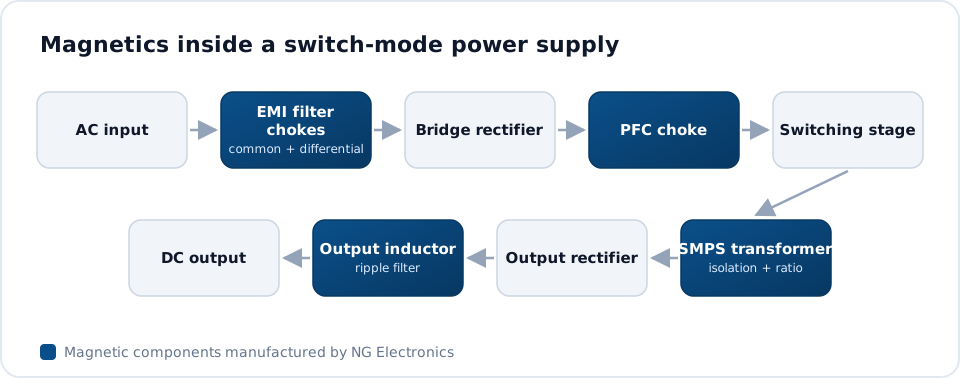
Consistency in the magnetic parts matters here. NG Electronics tests every choke for inductance, DC resistance and hipot before dispatch, as outlined on its quality assurance page, and keeps batch records for traceability. During development, the prototype manufacturing service can supply alternative inductance values for comparison, and the EMI filter choke range covers 250 mA to 50 A for the final design.
Frequently asked questions
What is the difference between quasi-peak and average detectors?
A quasi-peak detector weights a signal according to how often it repeats, so occasional pulses read lower than continuous noise of the same amplitude. An average detector reports the mean level and responds mainly to continuous narrowband signals. Standards set a separate limit for each, and a product must meet both. A peak detector reads highest of all and is used for fast initial scans.
Do I need an accredited laboratory for pre-compliance testing?
No. Pre-compliance measurements can be made in-house with a LISN, a spectrum analyser and a reference plane, and they are valuable for comparing design options. They do not replace the formal test, because the laboratory environment, receiver and set-up are calibrated to the standard. Allow margin for the difference between the two, and treat in-house scans as relative measurements.
Can a different choke alone fix a failing scan?
Sometimes. If the failure is common mode noise in the lower part of the band, a choke with higher inductance or a higher-permeability core often provides the missing margin. If the noise is differential mode, or is bypassing the filter through layout, changing the choke will not help. NG Electronics can supply sample chokes in several values so that the effect can be measured directly.
About NG Electronics
NG Electronics is a leading ISO 9001:2015 certified manufacturer of toroidal power inductors, common mode chokes, ferrite core transformers, line filter inductors, drum core inductors and custom wound magnetic components, based in Pune, India. Every part is wound and 100% electrically tested in-house. Share your pre-compliance scan and filter schematic with NG Electronics at sales@ngelectronics.in to receive a choke recommendation and technical quotation within 24 working hours. Overseas enquiries are welcome.




