In a switching converter the inductor current is never perfectly flat. It ramps up while the switch is on and ramps down while it is off, producing a triangular waveform riding on the average load current. The peak-to-peak height of that triangle is the inductor ripple current, and it is the first quantity most designers calculate, because inductance, peak current, core loss and output capacitor stress all follow from it.
Choosing the ripple is a compromise, not a calculation with one right answer. A small ripple needs a large inductance and a physically bigger part; a large ripple shrinks the inductor but raises losses and peak stress elsewhere. This article explains where the ripple comes from, works through an example and describes how the choice influences the component that NG Electronics or any other winding house will eventually build for you.
Key takeaways
- Ripple follows directly from V = L di/dt applied over the switch on-time.
- For a buck converter, ripple equals (Vin – Vout) x D / (L x f).
- A ripple of 20 to 40 percent of full load current is a typical starting point.
- Peak current, not average current, must stay below the saturation rating.
Where inductor ripple current comes from
The relation V = L di/dt says that a fixed voltage across an inductor makes its current change at a fixed rate. During the on-time of a buck converter the voltage across the inductor is the input minus the output, so current rises linearly. During the off-time the voltage is the output alone, reversed, so current falls linearly. In steady state the rise equals the fall, and the difference between the highest and lowest points is the ripple.
Because the on-time equals the duty cycle divided by the switching frequency, the buck ripple is (Vin – Vout) x D / (L x f). Boost and buck-boost stages use the same reasoning with the input voltage across the inductor during the on-time, giving Vin x D / (L x f). Higher inductance or higher frequency reduces ripple in direct proportion, which is one reason wide-bandgap switches running at higher frequencies allow smaller magnetics.
A worked buck converter example
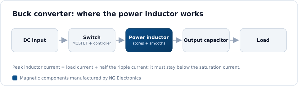
Take a 24 V to 12 V buck stage delivering 3 A at 200 kHz with a 47 µH inductor. The duty cycle is 0.5 and the voltage across the inductor during the on-time is 12 V. Ripple is therefore 12 x 0.5 / (47 µH x 200 kHz), which comes to about 0.64 A peak to peak. That is roughly 21 percent of the load current, and the peak inductor current is 3 A plus half the ripple, about 3.32 A.
Now account for tolerance and input range. With an inductor at the low end of a 20 percent tolerance band the ripple increases to about 0.8 A, and if the input rises to 30 V the duty cycle falls to 0.4 and the ripple increases again, since the buck ripple is greatest at maximum input voltage. The saturation rating should exceed the resulting worst-case peak with margin. A step-by-step method is given in how to select an inductor for a DC-DC converter, and the inductance calculator gives a quick first estimate.
Choosing the ripple ratio
The ripple ratio is the peak-to-peak ripple divided by the full load current. A value between 20 and 40 percent is typically used as a starting point for continuous conduction designs. Below that range the inductor grows large and the converter responds more slowly to load steps, because a big inductance limits how fast current can change. Above it, the RMS current in the switches and capacitors climbs and the core sees a larger flux swing.
Light load behaviour also depends on this choice. When the load current drops below half the ripple, the inductor current reaches zero during each cycle and the converter enters discontinuous conduction unless it uses synchronous rectification. Some topologies are designed to run at very high ripple intentionally, for example boundary-mode power factor correction, described in PFC choke design and selection, where the peak current is twice the average and the choke must be sized accordingly.
- Low ripple: larger inductor, lower capacitor stress, slower transient response.
- High ripple: smaller inductor, higher peak and RMS currents, more core loss.
- Check the ripple at maximum input voltage and minimum inductance.
How ripple affects losses and heating
Copper loss depends on RMS current. For a triangular ripple on a direct current, the RMS value is the square root of the average squared plus the ripple squared divided by twelve, so at moderate ripple ratios the increase over the average is small. At high frequency, however, the alternating part of the current crowds towards the conductor surface through skin and proximity effects, and its effective resistance can be several times the DCR.
Core loss depends on the alternating flux swing, which is proportional to the ripple, not to the load current. A design with high ripple at high frequency can therefore run hot even when the direct current is well inside the rating. Material choice matters here: iron powder tolerates large direct currents but has higher loss under heavy ripple than ferrite or the better alloy powders. The mechanisms are set out in inductor core losses explained.
Specifying an inductor from the ripple calculation
Once the ripple is fixed, the specification follows: inductance and tolerance, peak current for saturation, RMS current for heating, switching frequency and ripple amplitude for core loss, and the allowed temperature rise. Stating the ripple explicitly helps the manufacturer select the core material. For moderate currents a part from our toroidal power inductors range or a drum core inductor for DC-DC converters may fit directly, without any custom tooling.
Higher power stages, such as the boost and output filter chokes in a photovoltaic system, often need a toroidal inductor for solar inverter duty wound with heavier or multi-strand copper. NG Electronics is an ISO 9001:2015 certified manufacturer in Pune, India, and works as a custom toroidal inductor manufacturer for such cases, checking inductance under bias on the approved sample so that the calculated ripple matches what the converter actually sees.
Frequently asked questions
What is a good inductor ripple current percentage?
A ripple of 20 to 40 percent of the full load current is typically used as a starting point for continuous conduction converters. It balances inductor size against capacitor stress and transient response. The best figure for a particular design depends on efficiency targets, available space, light load requirements and the loss characteristics of the chosen core material.
Does ripple current depend on the load?
In continuous conduction the peak-to-peak ripple depends on the voltages, duty cycle, inductance and frequency, not on the load current. The load only shifts the average level on which the ripple sits. If inductance falls under heavy bias because the core is approaching saturation, however, the ripple will increase at high load.
How do I reduce inductor ripple current?
Increase the inductance, raise the switching frequency, or use interleaved phases so that ripple currents partly cancel at the output. Each option has a cost: more inductance means a larger part or more turns and DCR, and higher frequency increases switching and core losses. NG Electronics can propose a core and winding once the target ripple is known.
About NG Electronics
NG Electronics is a leading ISO 9001:2015 certified manufacturer of toroidal power inductors, common mode chokes, ferrite core transformers, line filter inductors, drum core inductors and custom wound magnetic components, based in Pune, India. Every part is wound and 100% electrically tested in-house. Send your input and output voltages, load current, switching frequency and target ripple to NG Electronics for a technical quotation within 24 working hours and a sample for laboratory approval.