


Leakage inductance in common mode chokes is usually described as an imperfection, yet most mains filters depend on it. A common mode choke has two or more windings on one core, arranged so that the flux from the normal load current cancels. The cancellation is never complete. A small part of the flux from each winding takes a path that does not link the other, and that uncoupled flux appears electrically as an inductance in series with the line.
This series inductance filters differential mode noise at no extra component cost, but it also sets a limit on how much current the choke can carry before the core begins to saturate. Understanding where it comes from, how to measure it and how winding style changes it allows a designer to specify the right amount. NG Electronics, an ISO 9001:2015 certified manufacturer in Pune, India, controls this parameter on its common mode chokes through winding layout.
Key takeaways
- Leakage inductance is the uncoupled flux of each winding, seen as series differential mode inductance.
- It is typically of the order of one per cent of the common mode inductance for sectional toroidal chokes.
- It provides differential mode filtering but can saturate the core at peak line current.
- Sectional winding raises leakage; bifilar winding minimises it.
What leakage inductance in common mode chokes actually is
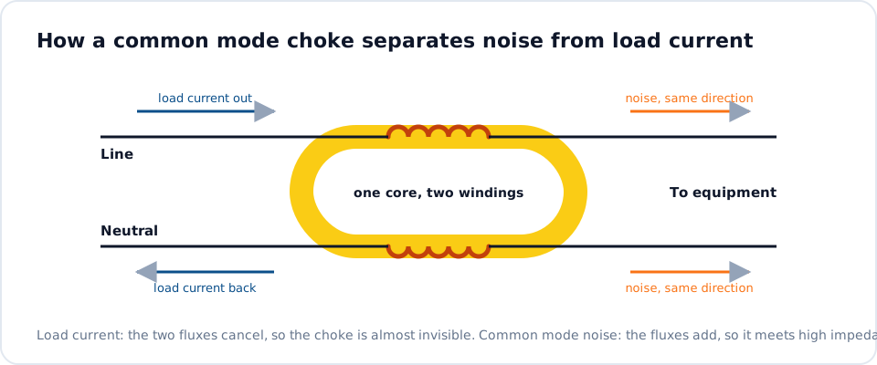
Consider a toroidal choke with two equal windings on opposite halves of the core. Common mode current flows the same way through both, their fluxes add around the core, and the choke shows its full inductance. Differential mode current, the normal load current, flows in opposite directions, so the fluxes around the core cancel. However, some flux from each winding leaves the core, crosses the air between the two windings and returns.
That flux links only the winding that produced it. It is not cancelled, so the choke presents a small inductance to differential mode current. The concept is identical to the leakage inductance of a transformer, described in our article on transformer leakage inductance. For toroidal chokes with separated windings it is typically of the order of one per cent of the common mode inductance, though the figure varies widely with geometry.
How to measure it
Two simple methods use an LCR meter. In the first, short-circuit one winding and measure the inductance of the other; the shorted winding cancels the mutual flux and the meter reads the leakage. In the second, connect the two windings in series so that their fluxes oppose and measure across the pair. For a choke with equal windings, both readings give the total differential mode inductance that the line current sees.
Measure at a frequency well below the self-resonance of the part, and state the method on the drawing, because the two approaches can differ slightly through winding resistance and capacitance. The common mode inductance is measured on a single winding with the other open. If you only know core dimensions and turns, the inductance calculator estimates the common mode value, but leakage depends on winding geometry and is best measured on a sample.
The benefit: differential mode filtering at no extra cost
Together with X capacitors on each side of the choke, leakage inductance forms a pi filter for differential mode noise. In many low- and medium-power supplies this is the only differential mode inductance in the filter, which saves a component and its copper loss. The relationship between the capacitors and the choke is set out in our article on X and Y capacitors with common mode chokes, including the limits on capacitor values.
The corner frequency follows the usual LC relation, using the measured leakage value and the X capacitance. Because leakage is small, the X capacitors do much of the work, and the result should be checked on a scan. One advantage of leakage flux is that its path runs largely through air, so the inductance remains fairly constant with current until the core itself approaches saturation, which is the subject of the next section.
The risk: saturation and stray field
Leakage flux still passes through part of the core, and unlike the main flux it is driven by the full line current. The flux density it produces is proportional to leakage inductance multiplied by current, so a choke with generous leakage and a high-permeability core can saturate on current peaks, including inrush and the crest of a rectifier input current. When that happens the common mode inductance collapses for part of each cycle and emissions rise.
This is why a choke that measures correctly on the bench can underperform at full load. It is also why high-current parts are designed with care over leakage: the high-current common mode choke constructions we build balance leakage against peak current. A second effect is the external field. Leakage flux in the surrounding air can couple into nearby tracks and components, so keep sensitive nodes and other magnetic parts at a distance.
Controlling leakage through winding style
Winding layout is the main control. Sectional or split winding, with each winding confined to its own sector of the core and a divider between them, gives the highest leakage and the best insulation between lines, which suits mains filters. Reducing the angle each winding covers increases leakage further. Bifilar winding, with the two wires laid together, gives very low leakage and suits signal and data lines where differential signals must pass unaltered.
Core shape and material also contribute, and UU-core chokes with windings on separate limbs typically show more leakage than toroids. When a design needs a defined value, state the target leakage inductance and peak current alongside the common mode inductance; the common mode choke selection checklist lists the full set of parameters. NG Electronics offers this through its custom toroidal winding and EMI filter choke services, with samples for verification.
Frequently asked questions
How much leakage inductance does a common mode choke typically have?
For toroidal chokes with windings on separate sectors, it is typically of the order of one per cent of the common mode inductance, and somewhat more for UU-core types with windings on separate limbs. Bifilar-wound chokes have far less. These are rules of thumb only; the actual figure depends on core size, turns and winding coverage, and should be measured.
Is higher leakage inductance always better for filtering?
No. More leakage improves differential mode attenuation, but it also raises the flux that line current drives through the core, bringing saturation closer at peak current, and it increases the stray field around the part. The right value gives the differential mode attenuation required while keeping the core clear of saturation at the highest peak current, including inrush.
Can leakage inductance be specified on a custom choke?
Yes. NG Electronics can wind to a target leakage inductance by adjusting winding coverage, separation and core selection, and can record the measured value on the test certificate supplied on request. Provide the common mode inductance, the leakage target with tolerance, the peak line current and the measurement method you prefer, so that both sides measure it the same way.
About NG Electronics
NG Electronics is a leading ISO 9001:2015 certified manufacturer of toroidal power inductors, common mode chokes, ferrite core transformers, line filter inductors, drum core inductors and custom wound magnetic components, based in Pune, India. Every part is wound and 100% electrically tested in-house. Send your common mode inductance, leakage target and peak current to NG Electronics at sales@ngelectronics.in for a technical quotation within 24 working hours and a sample for lab approval.




