
24 V industrial buck rails
Control cabinets step 24 V down to 5 V or 3.3 V for controllers and sensors.
Enquire now


NG Electronics · ISO 9001:2015 Certified Company
A practical guide on how to select an inductor for a DC-DC converter, written by the applications team at NG Electronics, an ISO 9001:2015 certified inductor manufacturer in Pune.
Knowing how to select an inductor for a DC-DC converter comes down to four checks made in a fixed order: inductance, peak current, heating and stray field. The inductor stores energy while the switch is on and releases it while the switch is off, so its value decides how far the current swings in each cycle.
DC-DC converter inductor selection goes wrong most often when a part is picked on inductance alone. Two inductors marked 22 µH can differ widely in saturation current, DCR and core loss, and those three figures determine whether the converter survives a load step or an overload. A datasheet value is also measured at small signal with no DC bias; under load current the inductance is lower, sometimes considerably so with a small core.
This guide walks through the reasoning in words, with one worked buck example, so you can apply it to your own input voltage, output voltage, load and switching frequency. Where a catalogue part does not pass all four checks at once, NG Electronics winds drum core and toroidal inductors to order in Pune and supplies a sample for evaluation on your board.
 ISO 9001:2015 certified
Each row is a figure you will meet on an inductor datasheet or in a converter calculation, with a note on how to use it.
| Inductance (L) | Sets the ripple. Calculated from input voltage, output voltage, switching frequency and target ripple. |
|---|---|
| Inductor ripple current (ΔI) | Peak-to-peak swing in each cycle. Typically chosen as 20% to 40% of full load current. |
| Peak current | Average inductor current plus half the ripple. Compare it with saturation current. |
| Saturation current (Isat) | DC level at which inductance has fallen by a stated percentage. Keep it above peak current with margin. |
| Rated current (Irms) | Thermal limit, typically the current giving a stated temperature rise. Compare it with RMS current. |
| DCR | Winding resistance in mΩ. Copper loss is RMS current squared multiplied by DCR. |
| Shielding | Shielded parts confine stray field near sensitive traces; unshielded parts typically give more current per size. |
| NG Electronics range | Drum core 1 µH to 1 mH; toroidal 10 µH to 10 mH standard, up to 25 A |
Figures such as saturation current and DCR depend on the design and are confirmed on the technical quotation for your part.
The same four checks apply to any non-isolated switching stage; only the governing limit changes from one application to the next.
Control cabinets step 24 V down to 5 V or 3.3 V for controllers and sensors.
Enquire now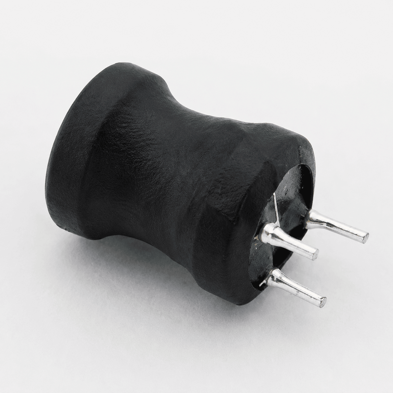
The inductor carries a near-constant DC current for hours, so temperature rise from DCR usually becomes the limiting check before saturation does.
Enquire now
In a boost converter the inductor carries the input current. Peak current is greatest at the lowest panel or battery voltage.
Enquire now
Low output voltages at high switching frequency call for small inductance values, low DCR and a shielded part placed close to signal circuitry.
Enquire nowStock parts you can order today. View details, add to cart or enquire for a custom variant.
Email your input range, output voltage, load current and switching frequency to sales@ngelectronics.in, or call or WhatsApp +91 83290 52861, Monday to Saturday, 9am to 7pm.
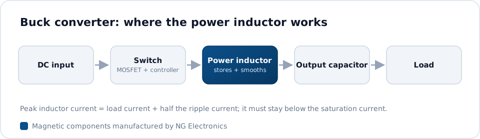
For a buck stage in continuous conduction, the inductor sees the output voltage in reverse while the switch is off. From V = L di/dt, the ripple is ΔI = Vout × (1 − D) / (L × fsw), where the duty cycle D is roughly Vout / Vin. Take 12 V in, 5 V out, a 2 A load and 300 kHz. D is about 0.42. Choosing 30% ripple gives a ΔI of 0.6 A, and rearranging the relation gives roughly 16 µH, so 15 µH is the practical choice.
With 15 µH the ripple becomes about 0.65 A, so the peak current is 2 A plus half of that, close to 2.3 A. The saturation current should clear this with margin, and should also clear the controller's current limit, because that is what the inductor carries during a short circuit or a hard start-up. RMS current is only slightly above the 2 A load figure, and that is the number to set against rated current and DCR.


A calculation gives you a target; a wound part has to hit it every time. NG Electronics is an ISO 9001:2015 certified company that winds and tests inductors under one roof in Pune. Every unit is electrically tested for inductance, DCR, Q factor, saturation current and hipot, so the figures you designed around are the figures measured on the parts that arrive.
If the calculated value falls between catalogue parts, send us the converter details instead of compromising. You receive a technical quotation within 24 working hours and a free sample to approve in your own lab, typically within 7 to 10 working days for a custom design. We ship across India from Pune, and enquiries from overseas design teams are welcome.
Call, WhatsApp or use the form with inductance, current and quantity.
Price, lead time and datasheet within 24 working hours.
Sample built in-house for your lab testing and approval.
Production with 100% electrical testing under ISO 9001:2015.
Packed with a test certificate, shipped across India or exported worldwide.
Answers about how to select an inductor for a DC-DC converter from NG Electronics, an ISO 9001:2015 certified company
Work in order. Choose a ripple current, typically 20% to 40% of load current, and calculate the inductance from input voltage, output voltage and switching frequency. Check that saturation current exceeds peak current and the controller's current limit. Check that rated current and DCR keep temperature rise acceptable. Then decide on shielding and package from the board layout.
A ripple of 20% to 40% of full load current is the typical starting range. Lower ripple needs more inductance, which means a larger part and a slower response to load steps. Higher ripple shrinks the inductor but raises peak current, output capacitor ripple and core loss.
No. Inductance falls as DC current rises, gradually in powder cores and more abruptly in gapped ferrite as it nears saturation. It also carries a tolerance, typically ±10% or ±20%. Run the ripple calculation with the lowest inductance you expect at full load and maximum temperature, not the nominal figure printed on the datasheet.
The method is the same but the currents differ. In a boost stage the inductor sits at the input, so its average current is the input current, which exceeds the load current by roughly the step-up ratio divided by efficiency. Size saturation current for the lowest input voltage, where input current is greatest.
Not automatically. More inductance lowers ripple, but in the same package it means more turns of thinner wire, so DCR rises and saturation current falls. It also slows the response to load changes. Staying near the calculated value and spending the margin on saturation current is usually the sounder choice.
Yes. Drum core inductors are wound from 1 µH to 1 mH in SMD, radial and axial formats, and toroidal power inductors from 10 µH to 10 mH as standard, with custom values beyond that. Share your voltages, load current, switching frequency and footprint, and a technical quotation follows within 24 working hours.
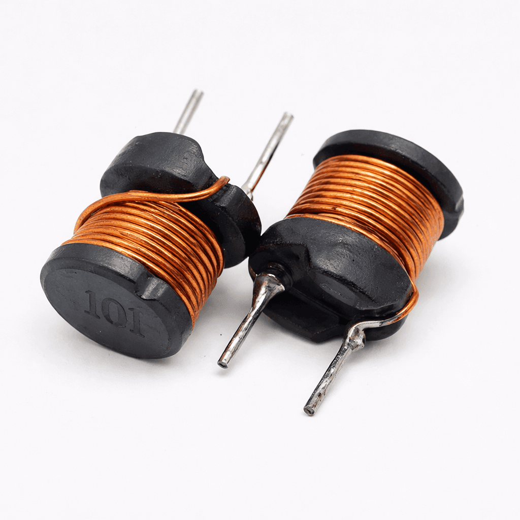
Drum core inductor for DC-DC converter designs, 1 µH to 1 mH, shielded or unshielded
Learn more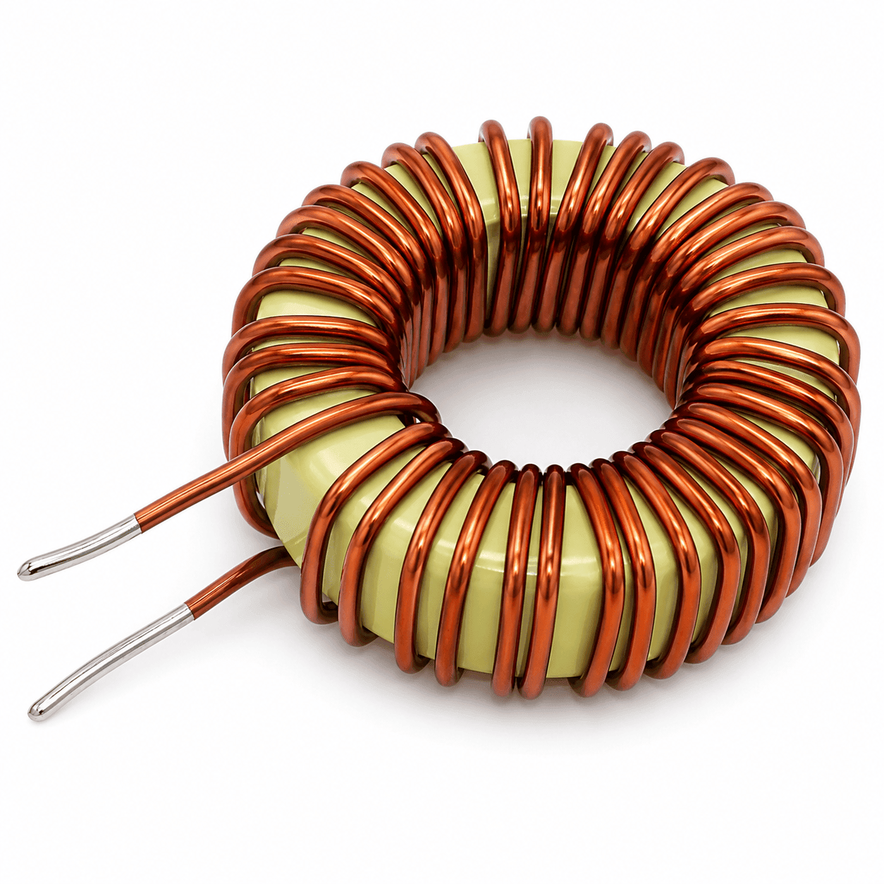
Inductance, saturation current and DCR explained in plain terms, with selection advice from an ISO 9001:2015 c
Learn more
Toroidal vs drum core inductors compared on stray field, current, size and cost by an ISO 9001:2015 certified
Learn more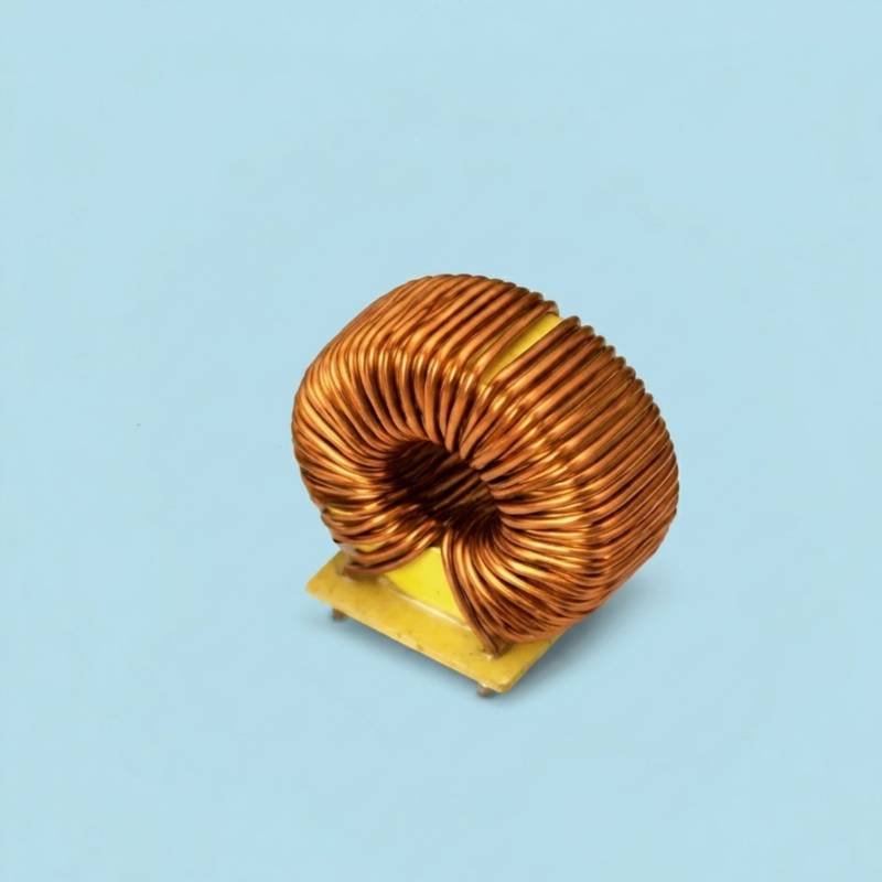
Estimate turns and inductance for your core.
Learn moreSend your specification or drawing for how to select an inductor for a DC-DC converter. NG Electronics is an ISO 9001:2015 certified company, and every enquiry is answered by our engineering and sales team in Pune.



These products are limited, checkout within

Smart configuration workspace setup.


