
Converter output inductors
In buck and boost stages the crest of the ripple tests saturation current, while the average load current tests the thermal rating.
Enquire now


NG Electronics · ISO 9001:2015 Certified Company
Inductance, saturation current and DCR explained for working engineers by NG Electronics, an ISO 9001:2015 certified manufacturer that measures all three on every inductor it ships.
Three lines on a datasheet decide whether a power inductor suits your circuit, and this page has inductance, saturation current and DCR explained one at a time. Inductance tells you how strongly the part resists a change in current. From V = L di/dt, a larger inductance means a slower current ramp for the same applied voltage. It also sets the stored energy, E = 1/2 L I², which is why inductance and current capability must always be read together.
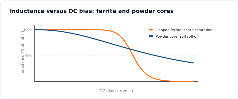
Inductor saturation current describes the limit of the core. As DC current rises, the core material approaches its maximum flux density, permeability drops and the inductance falls away. Manufacturers quote the current at which inductance has dropped by a stated percentage, typically 10%, 20% or 30%, so two parts are only comparable when the percentage matches. Ferrite cores with a discrete gap hold their inductance and then fall sharply; powder cores decline gradually.
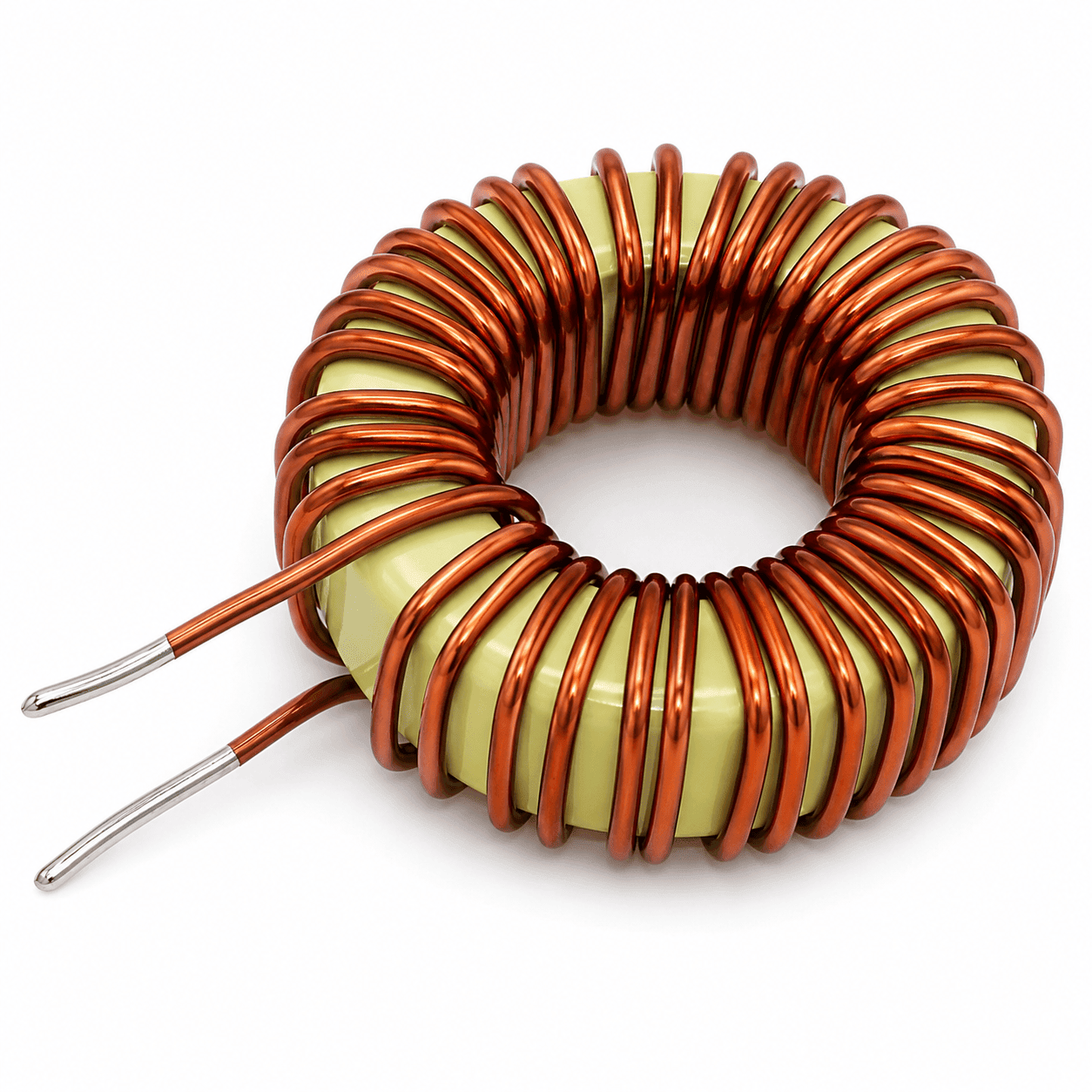
Inductor DCR is the resistance of the copper winding measured with direct current, usually given in mΩ. It turns load current into heat, and it is the main reason an inductor has a separate thermal rating. Lowering DCR needs thicker wire or fewer turns, which pushes against inductance and size. NG Electronics balances these three figures when designing toroidal power inductors, and verifies each one on finished parts with LCR testers.
 ISO 9001:2015 certified
The terms below appear on most power inductor datasheets. The right-hand column says what each one means and how to use it.
| Inductance (L) | Value in µH or mH at a stated test frequency and near-zero DC bias. Sets ripple through V = L di/dt. |
|---|---|
| Tolerance | Allowed spread on inductance, typically ±10% or ±20%. Design with the low end. |
| Saturation current (Isat) | DC current at which inductance has dropped by a stated percentage. Compare with circuit peak current. |
| Rated current (Irms) | Current that produces a stated temperature rise, typically 40 °C. Compare with RMS current. |
| DCR | DC winding resistance in mΩ. Copper loss equals RMS current squared multiplied by DCR. |
| Q factor | Ratio of reactance to loss resistance at a given frequency. Higher Q means lower loss at that frequency. |
| Self-resonant frequency | Frequency where winding capacitance resonates with the inductance. Operate well below it. |
| NG Electronics toroidal range | 10 µH to 10 mH standard, up to 25 A; custom 1 µH to 50 mH |
Always check the test conditions printed beside each figure.
Which of the three figures governs a design depends on the current waveform the inductor has to carry.
In buck and boost stages the crest of the ripple tests saturation current, while the average load current tests the thermal rating.
Enquire now
Heavy DC bias with ripple on top. Soft-saturating powder cores keep useful inductance at peak current, and DCR governs loss over long operating hours.
Enquire now
Overload and surge conditions push current well past nominal, so the inductance remaining at peak current matters more than the small-signal value.
Enquire now
Crossover and filter coils need stable inductance across the signal swing and low DCR, since winding resistance alters the filter response and wastes power.
Enquire nowStock parts you can order today. View details, add to cart or enquire for a custom variant.

Write to sales@ngelectronics.in or call or WhatsApp +91 83290 52861, Monday to Saturday between 9am and 7pm, and we will propose a part that meets all three.
The question of inductor rated current vs saturation current confuses many first designs because both are stated in amperes. They describe different failures. Exceed saturation current and the inductance collapses within the same switching cycle: the current ramp steepens, peak current climbs and the switch is stressed. Exceed rated current and nothing dramatic happens at once; the winding simply runs hotter than intended.
Copper resistance rises by roughly 0.4% per °C, so a winding running 50 °C above the temperature at which it was measured has about 20% more DCR than the datasheet figure. Ferrite saturation flux density also falls as the core warms, which lowers saturation current at exactly the moment the part is working hardest. The diagram shows inductance falling as DC bias current rises, which is why the stated drop percentage matters when comparing parts.


Numbers on a drawing only help if production parts match them. NG Electronics is an ISO 9001:2015 certified company, and all of its output is 100% electrically tested: inductance, DCR, Q factor, saturation current and hipot are measured on every unit. Winding and testing take place in-house in Pune, and batch records trace each delivery to its raw material and production date.
For toroidal power inductors the standard range runs from 10 µH to 10 mH at up to 25 A, on iron powder and ferrite cores, with heavier gauge or multi-strand copper used when a higher current is needed. Tell us the inductance required at your peak current, the DCR you can accept and the space available. A technical quotation is returned within 24 working hours, and a free sample follows for approval.
Call, WhatsApp or use the form with inductance, current and quantity.
Price, lead time and datasheet within 24 working hours.
Sample built in-house for your lab testing and approval.
Production with 100% electrical testing under ISO 9001:2015.
Packed with a test certificate, shipped across India or exported worldwide.
Answers about inductance, saturation current and DCR explained from NG Electronics, an ISO 9001:2015 certified company
Inductance is the small-signal value in µH or mH that sets how fast current changes for a given voltage. Saturation current is the DC level at which that inductance has dropped by a stated percentage because the core is nearing its flux limit. DCR is the resistance of the winding, which determines copper loss and heating under load.
Rated current is thermal: it is typically the DC current that raises the part's temperature by a stated amount, often 40 °C. Saturation current is magnetic: the current at which inductance falls by a stated percentage. Peak circuit current is compared with saturation current, and RMS current with rated current.
The saturation flux density of ferrite falls as temperature rises, so a ferrite inductor saturates at a lower current when hot than at room temperature. Powder core materials are typically less sensitive. For this reason saturation current should be checked at the highest core temperature expected in service, not only at the 25 °C figure commonly printed on datasheets.
Copper loss equals RMS current squared multiplied by DCR, so the loss grows quickly with load. At 5 A, a DCR of 20 mΩ dissipates 0.5 W. At high switching frequencies, AC winding loss and core loss add to this, so DCR is an important part of the loss picture but not all of it.
Only by using a larger core or a better core material. In a fixed size, more inductance needs more turns, which raises DCR and makes the core saturate at a lower current. Thicker wire lowers DCR but leaves room for fewer turns. Good design means deciding which figure matters most for the circuit and giving ground on the others.
Yes. Every unit is electrically tested for inductance, DCR, Q factor, saturation current and hipot before dispatch, using LCR testers and related equipment at the Pune facility. A test certificate is supplied with the order on request, and batch records provide traceability to raw material and production date.
Standard range 10 µH to 10 mH, up to 25 A.
Learn more
How to select an inductor for a DC-DC converter: ripple, peak current, DCR and shielding, from an ISO 9001:201
Learn more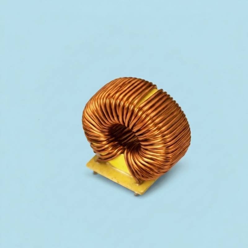
Ferrite vs powdered iron cores compared on loss, saturation and cost by an ISO 9001:2015 certified inductor ma
Learn more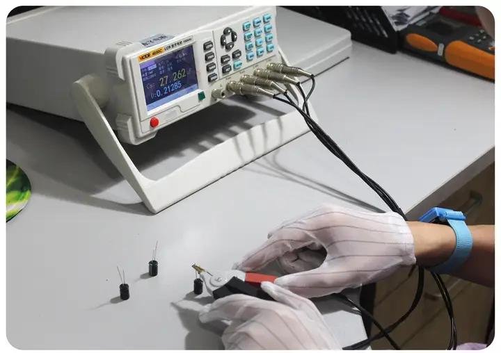
How every unit is inspected and electrically tested.
Learn moreSend your specification or drawing for inductance, saturation current and DCR explained. NG Electronics is an ISO 9001:2015 certified company, and every enquiry is answered by our engineering and sales team in Pune.



These products are limited, checkout within

Smart configuration workspace setup.


